 My Android phone battery only lasts a few hours when using the GPS to record tracking while hiking around the hills. So I was looking for a quick, cheap, simple and not too heavy solution.
This took about an hour to assemble and test from parts I had in the junk box.
Parts needed
This list is only a rough guide. There are many options for some of these parts.
- Voltage regulator module
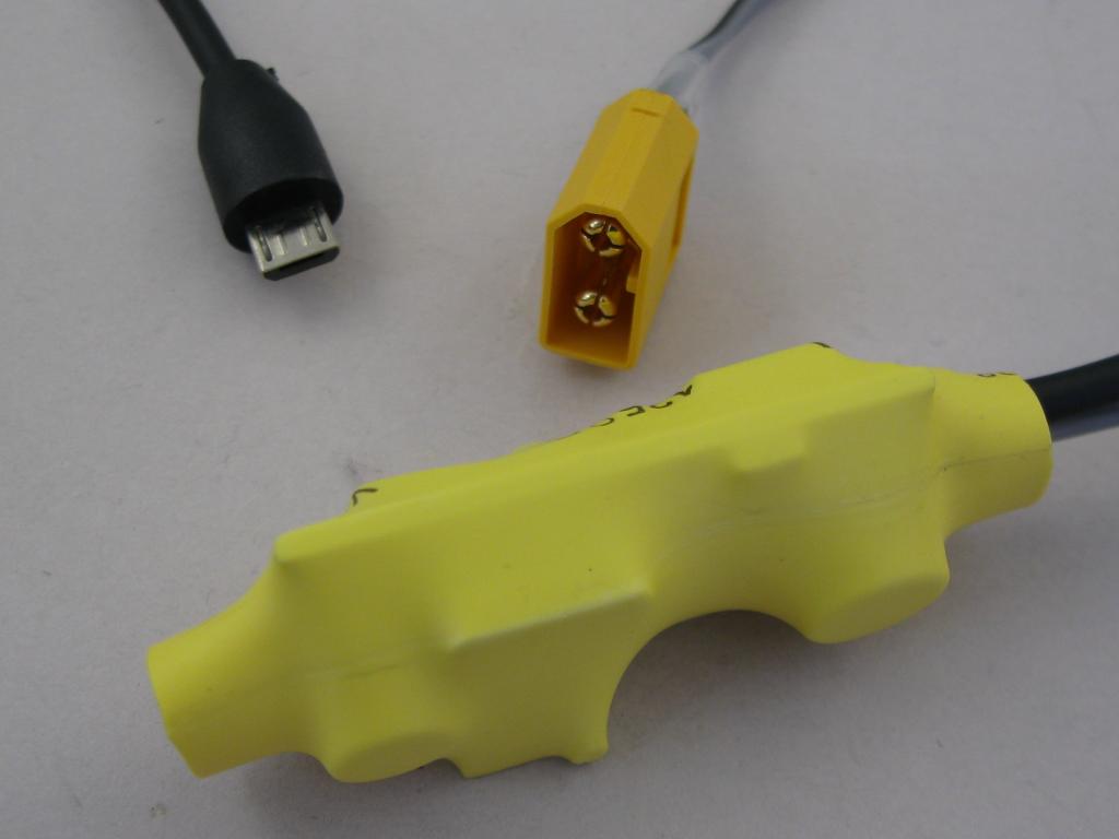
- Micro USB lead
- Battery lead with suitable battery connector
- PTC fuse (I had 2.5A on hand)
- 3A schottky barrier reverse protection diode
- heat-shrink misc small bits
- heat-shrink covering
Assembly
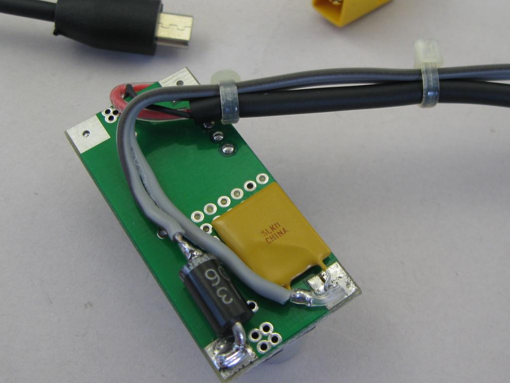 Start with a spare micro USB lead and cut the other end off. Test the large USB plug and lead end cut off to verify which wire cores are +5V and GND. Be warned – Get this wrong and you could destroy your phone. Strip, tin and sleeve the inner cores so that if the inner insulation fails or is punctured, it does not short to anything.
Attach a PTC fuse and reverse polarity protection diode to the back of the voltage regulator board. I used a 2.5A PTC and 3A schottky barrier series diode. The PTC is laying on the back of the regulator board. This will reduce the trip current as the regulator gets warm; a happy side effect.
Attach the USB lead and a short battery lead. I have a XT60 connector on the battery lead to work with RC model LiPo batteries.
Adjust the output voltage and test it before putting on the heat-shrink covering. Use a current limited power supply when testing. If you use a battery and anything goes wrong, you won’t get a second chance.
 Set the output voltage to about 5.2V to allow for a bit of volt-drop in the fine cored USB lead. Test it with a small load to ensure the voltage is stable and the output reliable. Only when everything else checks out, test it with a phone plugged in.
Heat-shrink the whole thing or enclose it to be protected and robust.
Specifications
- 6 to 24V DC Input
- 5.2V DC output (adjustable)
- 0.5A DC output
- Input reverse polarity protected and PTC fused
- 8mA approximate quiescent draw (no load connected)
- 240mA draw at 11.5V input and 0.5A load (charging phone)
Batteries
You can use any battery supply. If hiking, you just have to be prepared to carry it.Being a switchmode regulator, the higher the input voltage, the lower the current will be for a specific load. A 3-cell Lipo is ideal for me. 2-cell would work, or a car battery if camping.
A 3-cell 2200 mAh LiPo battery should charge the phone and run it at least all day. Time will tell. A LiPo alarm would be a good idea if you plan to push the limits. LiPo batteries will fail if run too low. Don’t do below 3.5V per cell.
Improvements
- replace the voltage control pot with fixed resistors
- better packaging – replace the heat-shrink
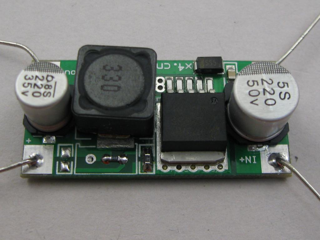 The voltage adjust potentiometer can be replaced with fixed resistors. There is one resistor already on the board, sense to GND. Remove the pot and install a 1K resistor. This provides an output of about 4.95V. To increase this to 5.15V, add a 6K8 resistor in parallel (across the top of) the existing fixed resistor.
The resistors are shown below the 330 inductor.
Update
- I have used these small switch-mode regulators in a few applications now. Sometimes the output voltage is a fraction high for comfort; 5.2-5.25V. The easy solution is to add a 47K resistor across the 1K resistor. This reduces the output by about 0.08-0.1V.
- The blue modules need different resistor values to provide 5V output. 1K2 in place of the preset-pot and 3K9 accross the existing resistor.