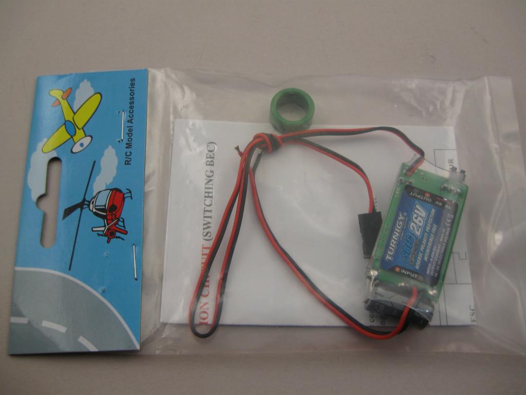
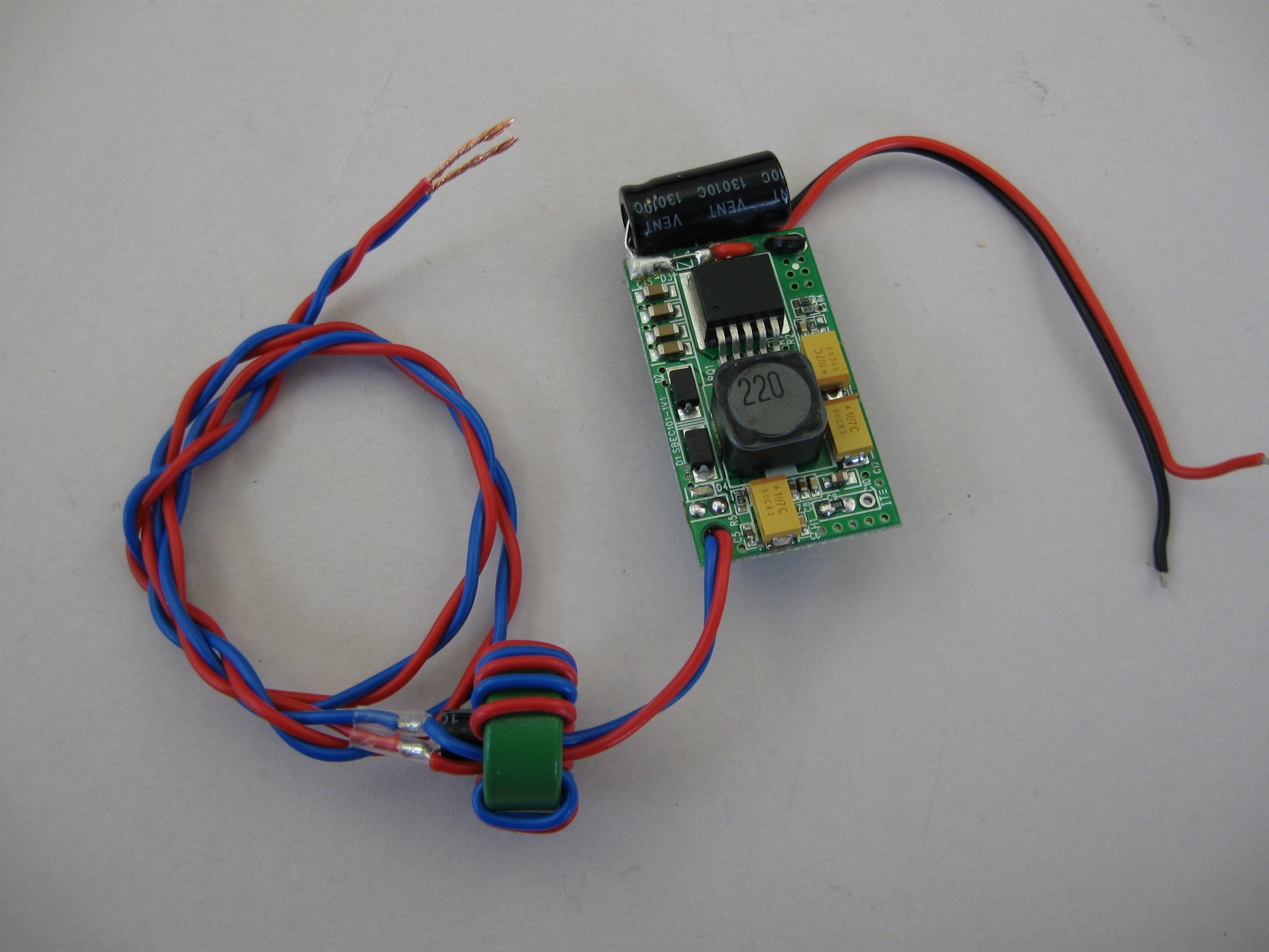
A Typical RC S-BEC
Before doing this I needed to know what it was capable of. This module is from Hobbyking and is rated to 26 Volts input and 5 Amps continuous output, at 5V or 6V jumper selectable. Bear in mind that the output rating is 5 Amps continuous. In most practical applications the average current draw probably won’t exceed 1.5 Amps. Safety and reliability are important when your model is at stake. That’s why I test this way. It may not actually deliver a continuous 5 Amps, but that does not mean it is not a good 1.5 to 2 Amp S-BEC. Any power electronics wrapped in heatshrink is going to be limited. To dissipate more than a watt or so you need a heatsink and/or some form of cooling. A 5A rating of a sealed unit immediately raises a red flag. |
Conclusion
If you plan to exceed 2 Amps output, on a 4-cell or less supply, you should remove and bridge the reverse polarity protection diode. Don’t blow it up by connecting the supply backwards. I have not loaded it beyond 2.5 Amps as I don’t need any more than that and I don’t want to destroy it. I will be running it set to 6V output and through an additional output filter to reduce the output noise. |
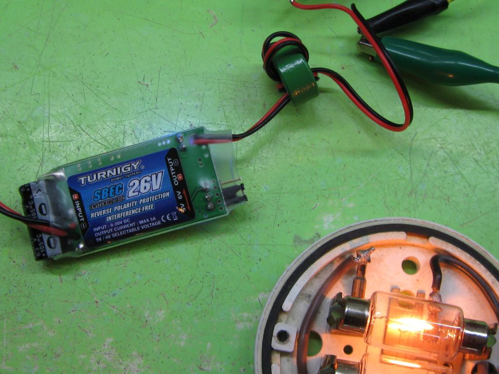
Testing the S-BEC
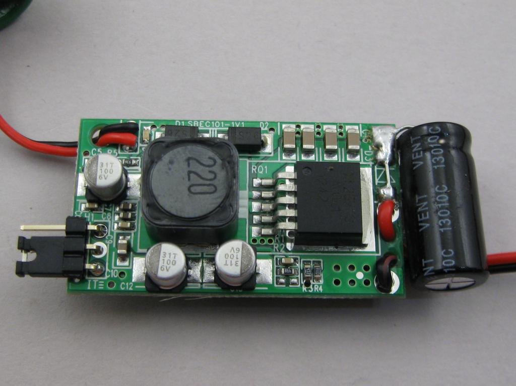
The main switching regulator is a XL2576S which is rated to deliver 3A (not 5A). This circuit has a 220uF 63V input capacitor, series input diode and three 100uF 6V output capacitors. The test set up uses a bench power supply set to 11.13 volts at the input of the S-BEC, which is set to 5V output and feeding a load drawing 1.45 Amps (a couple of small incandescent lamps). With this load, the input draw is 0.86A at 11.13V which is 9.57 Watts. The output at the end of the output lead (with filter in place) is 4.98V at 1.45A which is 7.22 Watts. This means a regulator dissipation of 2.35 Watts. With an ambient temperature of 28.5 deg-C (quite warm here today) the heatshrink covering is at 80 deg-C or too hot to hold on to. The output noise is about 220mV P-P and about 52KHz (19uS). While still covered, most of this heat seems to be coming from the main regulator and diode. There is a series reverse protection diode on the input (S2B) that is in contact with the input filter capacitor, which is making the capacitor very hot (about 66 deg-C); not good for long term reliability. The S2B diode is rated 1.5A and drops 0.79V at 0.86A; 0.68 Watts, explaining why it gets hot. The main switching inductor (220) is the other major source of heat. With the heatshrink covering removed, the main regulator runs about 78 deg-C and the inductor at 70 deg-C. Swapping to a variable load set to draw 2A. The input draw is 1.24A at 11.1V for 13.76 Watts. The output is 4.87V at 2A for 9.74 Watts. A loss of 4.02 Watts. The regulator is now at 105 deg_C and the inductor at 88 deg-C. Noise P-P is now about 200mV. The reverse protection diode loss is now 0.98 Watts. The output wiring is a bit small, resulting in a volt-drop of 0.1V per amp over both +ve and gnd. When set to 5V you get 4.8V out at 2 Amps.
|
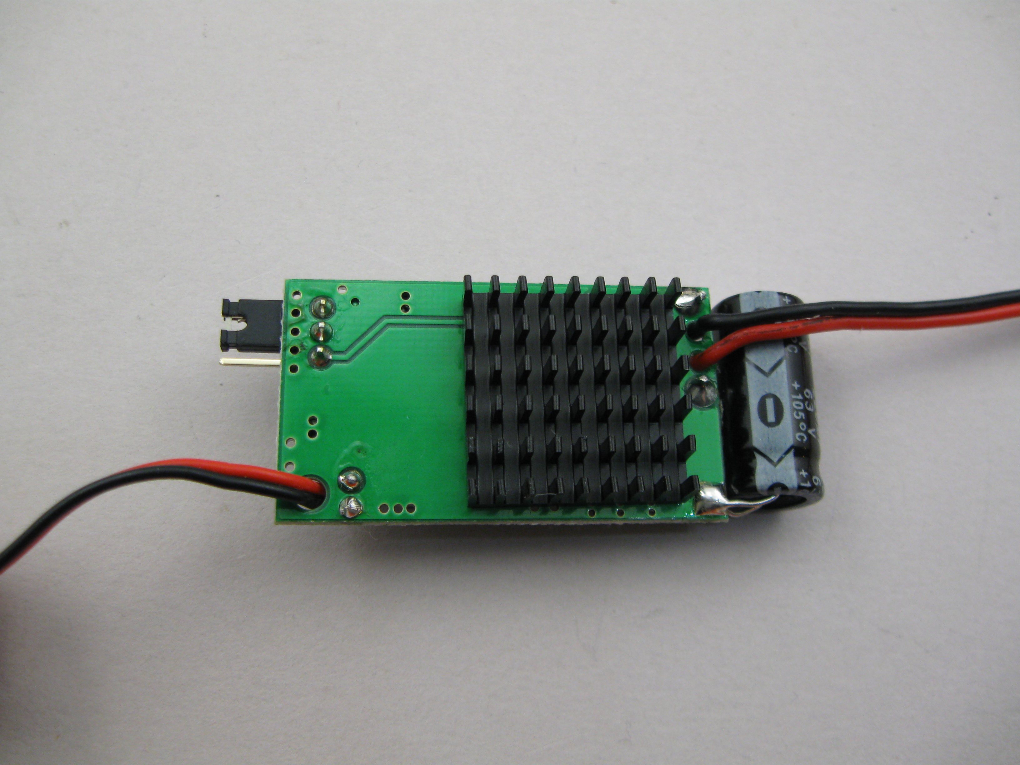
Heatsink Test
With the small stick-on heat-sink on the back of the circuit board, the temperatures dropped slightly to 82 deg-C and 71 deg-C. The heatsink is running at about 88 deg-C. Load to 2.5 AmpsWith the heatsink, running the load at 2.5 Amps results in a 1.6A input current at 11.1V. This exceeds the continuous rating of the reverse protection diode. The heatsink temperature rises to 103 deg-C with the other temperatures at 118 deg-C and 85 deg-C. Other ImprovementsThe output capacitors are 100uF 6V aluminium electrolytic. Considering that the output can be set to 6V, using a 6V rated output capacitor is cutting it a bit fine when failure is probably going to hurt. I will replace these 3 capacitors with tantalums rated 10V or 16V and do some more testing. The voltage select jumper can also be replaced with a soldered link. Mostly just to tidy it up. Removing the jumper defaults the output to 5V. Update:
The wiring is 0.5mm cores from security cable. The filter includes a 220uF 10V capacitor. Output noise is now about 45mV P-P with a 2 Amp load. With 6V output selected, you only just get 6V and under load it drops slightly. I’m still getting 5.8V at 2 Amps. I also increased the output load briefly, just to see how it would cope. At 3.5 Amps it still delivers 5.5V. That’s as far as I went; But not bad. |
NotesTemperatures measured using a Digitech QM-7223 infrared thermometer. |

.