What’s Current
 Looking to see what is current, well supported and/or well documented, open-source, available and at a reasonable price.
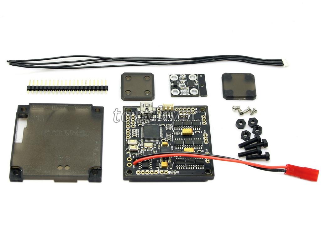
There seems to be some activity at the moment around the StorM32 brushless gimbal controller (BGC). It looks to be quite well documented.
Unfortunately, no Linux support. Although it claims to be open-source, that doesn’t apply to the firmware. Firmware, being such a large part of the project, I say it is not open source, as you could not recreate or support it without the source code.
The controller is available on Ebay: HERE and HERE.
The main support site (wiki) is : HERE, with Getting started HERE.
The RC Groups thread is: HERE.
Configuration Programs and APPs
I am not a fan of controllers (especially closed-source) that rely on configuration programs or Apps. Eventually the support community moves on, the operating system moves on and the project fades away. This is not a problem for the hobbyist who jumps to the next best thing every 6 months anyway. It is a problem for anyone wanting to get it working and keep using it for the next 5 years or more and who occasionally wants to set up another one the same.
AlexMos and Basecam
I looked at these controllers some time ago but decided not to use them due to it not being entirely open and there being some sort of lock in with the firmware and some boards.
I have just had a look at three of these boards from different suppliers and the PC configuration program. I had to fire up the old Windows XP because I couldn’t get the Linux Java version to run and as it was just a passing look it was not worth spending any more time on.
The hope was to get a couple of them working; but after several hours of reading and experimenting they were abandoned back to the box.
It probably works once you are experienced and familiar with it but from a casual user point of view, the configuration program is too complicated. The results of repeatedly connecting boards to PC were inconsistent and quite confusing. Some parts of the program screen offer help clues on mouse-over. A great way to provide assistance to the casual user. But many of the import sections and buttons do not. Progress messages appear and disappear and you cannot scroll back to find out what happened. Some messages are not very descriptive.
If you are keen and happy to spend some time on this, it will probably work.
Considering the processing power:
There is no need to have just a configuration program or App. There should be plenty of CPU performance and memory available on-board to include a basic command line interface (CLI). This would be fantastic with a Bluetooth interface and a simple terminal on a PC or phone for basic setup and adjustment. And it would be completely future-proof.
Probably few of you playing along now are old enough to remember the days of DOS when equipment like this connected using RS-232 and you needed a serial terminal like Cross-Talk. The equipment provided a text screen of info and a command entry cursor. If you were lucky, it was in colour and the cursor mover around the screen to edit values. The good old days when connecting to the equipment and editing the config was about the least of your problems. What’s amazing is that you can plug a terminal into a 30+ year old box and it still works. It was totally OS and App independent.
These days you must have the correct OS, app or browser and the correct version, correct drivers etc. and it may work. IMO, too much value is placed in the bling of a GUI and not enough in real function or how long it will last. I guess these days everyone is thinking throw-away and can’t understand that hardware may last more than a year.
Storm32 BGC First Impressions
The hardware looks OK. Although I wonder about the wisdom of using TC4452 mosfet driver chips to drive inductive motor loads. I prefer not to use single-source parts in such applications. Also, there is no protection on the camera-IMU interface and the incoming power supply filtering seems a bit light.
I have a laptop that dual boots into an old Windows-XP install; I don’t normally use Windows. The GUI program seems to run OK (after the long startup delay). XP detected the board and installed the ST USB driver without any fuss. The V080 GUI would not connect to my board saying I needed V068; so I located and downloaded that. Just un-zip and double click on the big .exe file to run the GUI; nice and simple.
The V068 GUI connects to the board reliably and the main functions seem to work. A bit of tinkering later and a few Youtube videos, I decided that it would probably work quite well once the gimbal was finished off and I find my way around the quirks of the GUI – some odd terminology and adjustment, up-down reversed. At first the GUI seems quite confusing and there are lots of bits that are not explained.
Time to upgrade to the latest version; V080. Seems easy enough after looking at the wiki.
CAUTION: the wiki mentions a USB interface but doesn’t comment on the 5V or 3.3V compatibility. Does using a 5V adapter risk damaging the board ??? PROBABLY. It’s not worth the risk, but I only had a 5V adapter handy. To minimize the risk I put a series 1.2K resistor in the TXD line from the adapter and didn’t connect the +5V (VCC).
I’ve got plenty of these cheap 4-wire USB-serial adapters; don’t know the chip, but the old Windows-XP seems to be OK with them.
First major problem, the re-flashing tool in the GUI doesn’t work with Windows-XP. It’s stupid things like this that annoy me the most and IMO hold back what could be a great system. See the heading above “Considering the processing power”.
Some research later and I downloaded a flash tool from ST, HERE, about 34MB of zip file that provides a program that Windows installs. This then allowed erasing and re-flashing.
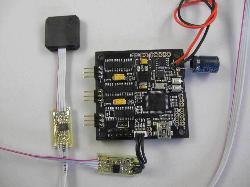
While re-flashing I also added the Bluetooth module to the back of the controller board. It seems to be working. The GUI was able to configure it.
Having re-flashed the board to V080 and now running the latest GUI – lets try again.
After a bit of experimenting, the GUI connection to the controller now seems to be less reliable. It often reports connection failures, requiring a restart; this didn’t happen at all while experimenting with V068. Removing the Bluetooth module from the back of the board didn’t seem to help, so that’s not the problem.
There is still a problem with Camera-IMU errors after enabling the pitch or roll motors. Likely noise in the long (400mm) IMU wiring, A lot more testing with different wire lengths and it’s confirmed to be motor switching noise causing the IMU connection to fail. Comments suggest that the IMU wiring should not exceed about 150mm; but this gimbal will need closer to 700mm. I wonder how reliable it would be at 150mm given that there is not much room for increase before it fails.
The next step is to experiment with I2C buffers and shielded wiring. As it turned out, the buffers seem to have solved the problem and shielded wire is not required.
I2C Buffers – Camera Sensor
The boards are small enough to be covered with some 9.5mm heat-shrink I have spare. The boards pass 3.3V power through to the sensor, providing some capacitive filtering. For greater robustness, the link section between the boards can be powered and have signal levels up to 12V. |
Installation on Gimbal
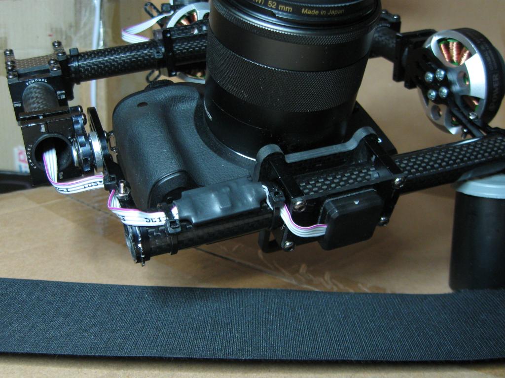
The buffer is soldered directly to the slip-ring wires. |
|
I used ribbon cable for the lead between buffer boards. It contains a reasonable amount of copper in many fine strands, is robust and flexible and solders easily; the plastic doesn’t shrink up the wire when heated. |
|
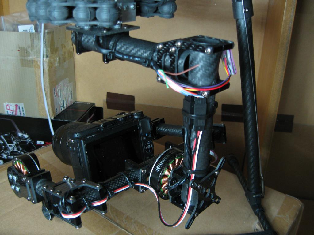
So far it is working great. No reported sensor errors, even when the tuning is off and the gimbal is twitching about. When powered it boots up and settles down with a solid green LED on the controller; which it would not do before the buffers, even without the slip-ring and the sensor wiring well clear of everything else. The motors are:iPower Gimbal Brushless Motor GBM4008-150T. For camera range: 400-800g
These motors don’t have very robust securing of the leads at the motor. The wiring needs to be secured so as not to be damaged by vibration or pulled from the motor. |
.
Hi,
Please can you tell me your batetry voltage used whith the gimal?
Thanks
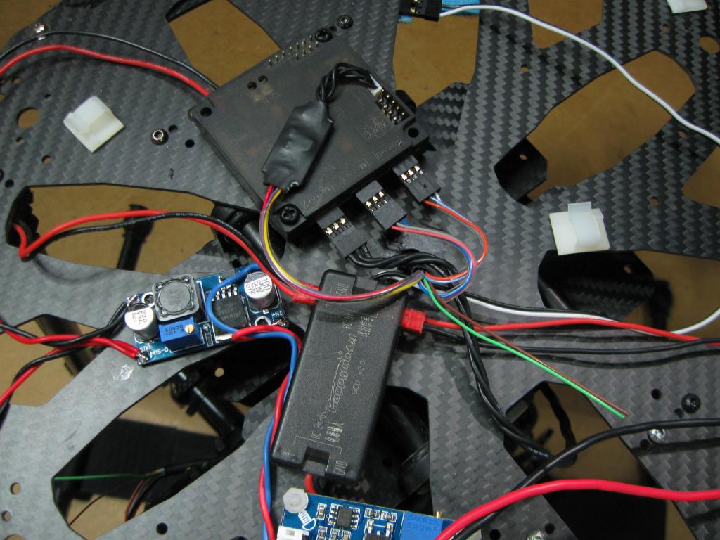
The battery is a 6-cell LiPo, so the voltage is 20 to 25 volts. But there is a voltage regulator providing a smooth 12.0 volt supply to the gimbal controller. The regulator is a common low-cost variable type that accepts up to about 35V input. These are good for 1 to 1.5 Amps continuous and up to 3A for short periods without a heatsink.
Looks good Paul. Will you add a capacitor to the Storm32 board as you have done on the top picture?
Nice work, very tidy.
Cheers, Brian.
Yes I will. It weighs little and just makes the power supply a little more robust. Still some tidy up to do on the wiring.