Update – repairs
Water damage – September 2017 it stopped working. The seal plug in the top of the antenna tube failed and water got in. When the water level got to the lowest power connector it corroded and went off. The only real failure was the amplifier directly under the antenna – fried 🙂
This is a good opportunity to check it out and do some mechanical upgrades. I am switching the ethernet lead to a waterproof socket-plug on the box, and replacing the antenna tube with PVC and a better cap. Also adding a second waterproof connector for a POE camera. But first a 2-3 week wait for the new amplifier to arrive.
 The Original Story and Build
The original wireless AP on our roof is running DD-WRT. The new one detailed here is running OpenWRT. DDWRT is easier to use but OpenWRT seems to be more configurable.
New features include a better TP-Link wireless router board, a booster and temperature controlled fan in the box. It’s still POE powered at 35V-DC on a single Cat-5e ethernet cable.
Wireless Router
The router is a TP-Link TL-MR3220, stripped for just the board. I chose this router because it’s low-cost and has one external antenna. There is a second antenna on-board; not sure what it’s doing. I replaced the long-legged LEDs with SMD types and soldered the power supply wiring direct to the board. The through-hole components had quite long leads sticking through, so these were trimmed.
Wifi Booster Amplifier
 Why a booster: no reason really. The output power of the router/AP board is turned well down, so the overall output is not too high.
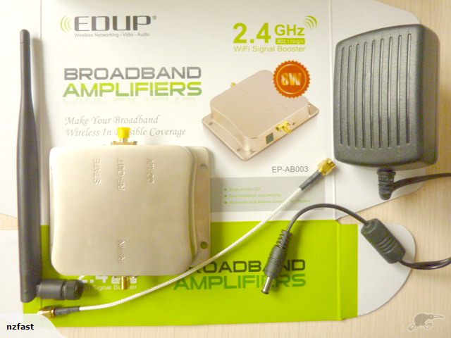
The Booster is a EDUP WIFI Booster Amplifier model EP-AB003. Chosen because it was cheap and available locally. Output power can be reduced by setting a lower output power in OpenWRT. A 2A switch-mode regulator drops the 20-35V DC down to 12V-DC for the booster. This regulator has an extra brass sheet heat-sink fin added.
Booster Specs:
- Weight: 750g
- Size : 103*77*21mm
- Support Standard: IEEE 802.11b/g/n
- Frequency: 2400-2500Mhz
- Working Pattern: TDD
- RF Output Power: 39dBm(8W)
- Input Trigger Power: Min:3dBm, Max: 20dBm
- Transmit Gain: 17dB typical
- Receiver Gain: 11dB typical
- Switch Time Delay:>1us
- Noise Figure: 30dB(typical)
- Working Voltage: 6-18VDC,12V/2A
Construction, POE and Fan Control
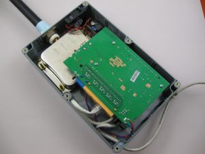
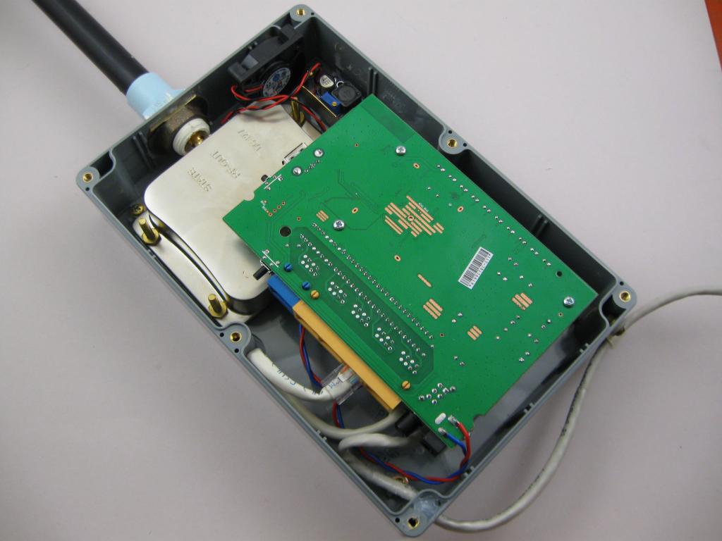
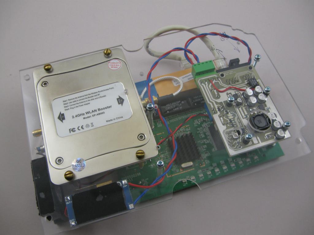 The various components are mounted to a acrylic sheet gear tray. All of this only just fits into the plastic outdoor enclosure.
The POE voltage regulation for the router board and temperature controlled fan is all handled by a board I designed 4-5 years ago for this purpose and camera housings. The heating function is not used here, but the fan will still run when cold or hot.
The main Cat-5e Feed cable is 5 meters and hard-mounted to the enclosure through a double wall section and sealed in the gap with silicon RTV. I used waterproof ethernet connectors last time, but decided they were not worth the expense this time.
The POE board takes the incoming ethernet cable and diverts the AC/DC power through a 12V switch-mode regulator for the router board. A rectified HV DC is supplied to a separate regulator for the booster.
A small PIC micro uses a thermistor to monitor the temperature in the box and control a small fan. This just evens out the temperature in the box to prevent any one part becoming too hot.
Antenna
 This is a omnidirectional 16dbi mounted directly to the booster and enclosed in 15mm plumbing fitting and tube to be waterproof.
Only the inner workings of a standard rubber-duckie type 2.4GHz wifi antenna are used.
The bottom end is beefed up and covered with heat-shrink to improve strength and vibration resistance.
Enclosure
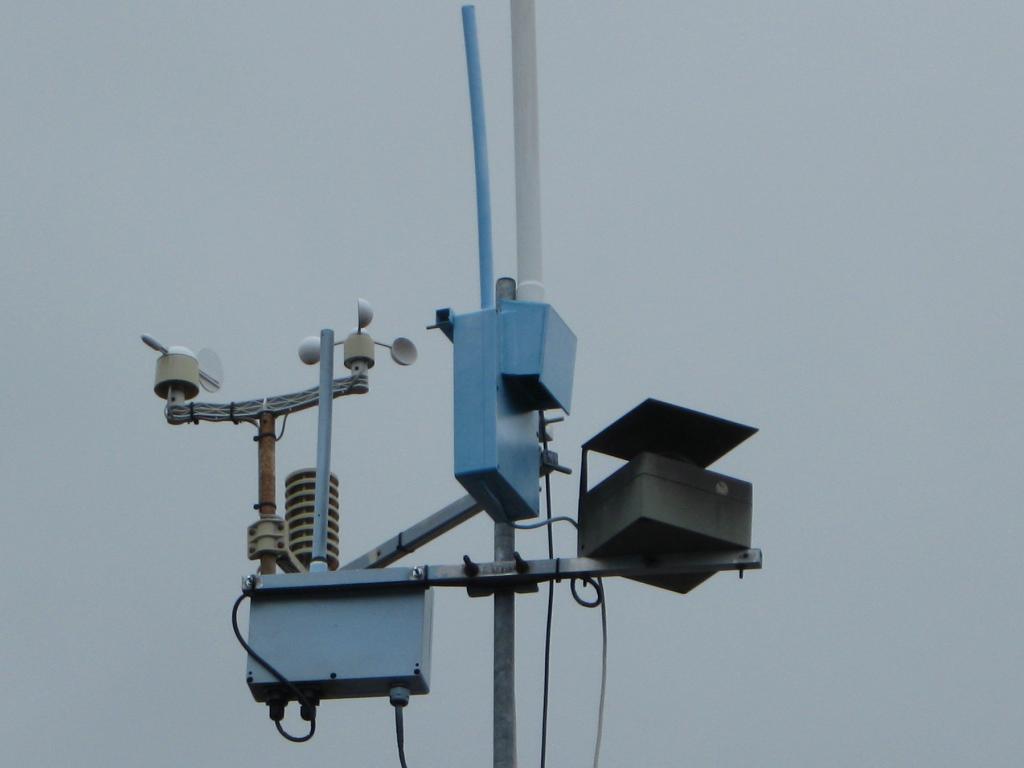 It is the blue box in the centre in this picture.
At this location it has to withstand direct rain, hail and snow briefly every few years, and ambient temperatures between -10 and 40 degC. The enclosure is sprayed sky blue to reduce heating in the sun and to provide a bit of extra UV protection.
A low-cost waterproof plastic enclosure mounted vertically with antenna on top and cable entry at the bottom.
With just the standard seal and no extra goop, the only ventilation is through the Cat-5e cable; effectively venting the enclosure into the roof of the house. This has proven to be very successful in the past with years of reliable operation of wifi and camera gear. Trying to completely seal an enclosure never really works and condensation will be a problem. Venting directly outside is also a problem.
Cooling
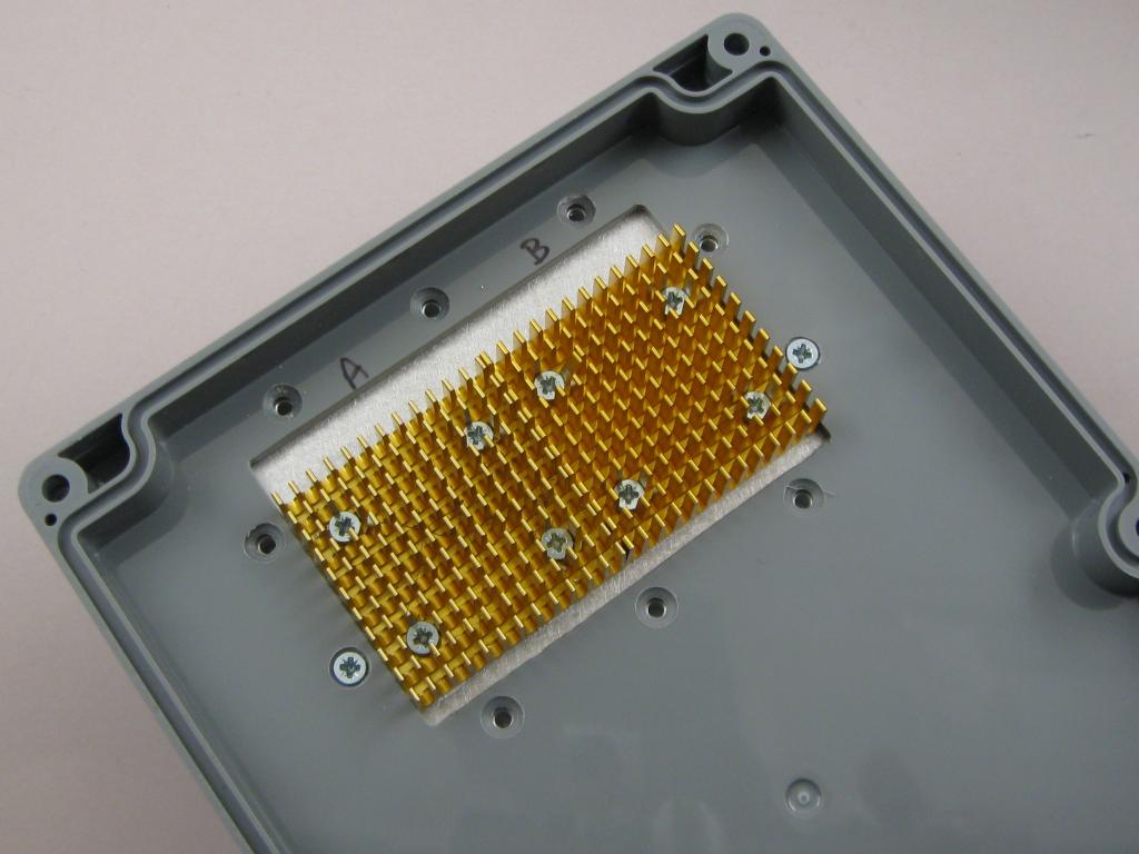 To avoid making holes in the enclosure a a passive heat transfer system was used. A larger heat-sink on the outside mounts a smaller heat-sink on the inside if it is cooler outside the inside air will be cooled. The large heat-sink is drilled and tapped for 3mm machine screws.
The internal fan circulates warm air inside the enclosure. Convection of wind outside move air over the external heat-sink.
A plastic cover on the outside keeps the sun off the heat-sink but allows air-flow up through the heat-sink. This is just made from 5mm Foam-PVC sheet glued to the outside and painted with the enclosure.
This seems to have worked well so far. We have not had any reliability problems in almost 2 years.