THE FIRE DENYER INSTALLATION GUIDE
The Fire Denyer must be installed by a registered electrician
The Fire Denyer is supplied with a User Manual & Installation Guide. This may be viewed on the “User Manual” page of this website.
General Installation Notes
- Use the correct tools – especially screwdrivers. Damage can result from using screwdrivers that are too big and when terminals are over tightened.
- Use the correct stranded cable for low voltage wiring. Typically 0.4-0.5 square-mm security cable.
- Strip the correct length and twist the strands before inserting wires into terminals.
- The Fire Denyer Controller is usually best installed near the kitchen light switch or somewhere handy for convenient operation.
- A standard single gang flush box will house The Fire Denyer Controller. The backup battery sits on a dwang near the flush box.
- Power supply to The Fire Denyer can be fed from a light switch, but it is best connected to its own supply on the switchboard before RCD supply, maximum 16 amps.
- A smoke detector is usually installed just outside the kitchen area. Additional smoke detectors are installed in all other areas considered at risk, for example bedrooms, lounge and laundry. Heat detectors may also be connected if required and would normally be placed closer to the cooking appliance.
- The contactor requires two spaces on the switchboard. If there is no space available it may be housed adjacent to the switchboard in a suitable enclosure.
- Follow the wiring diagram for correct installation. Incorrect wiring may cause damage to the equipment.
The Fire Denyer Controller
 Connections are shown in the wiring diagram.
Low voltage wiring connects to the smoke detectors and Flashing Alerters (if installed).
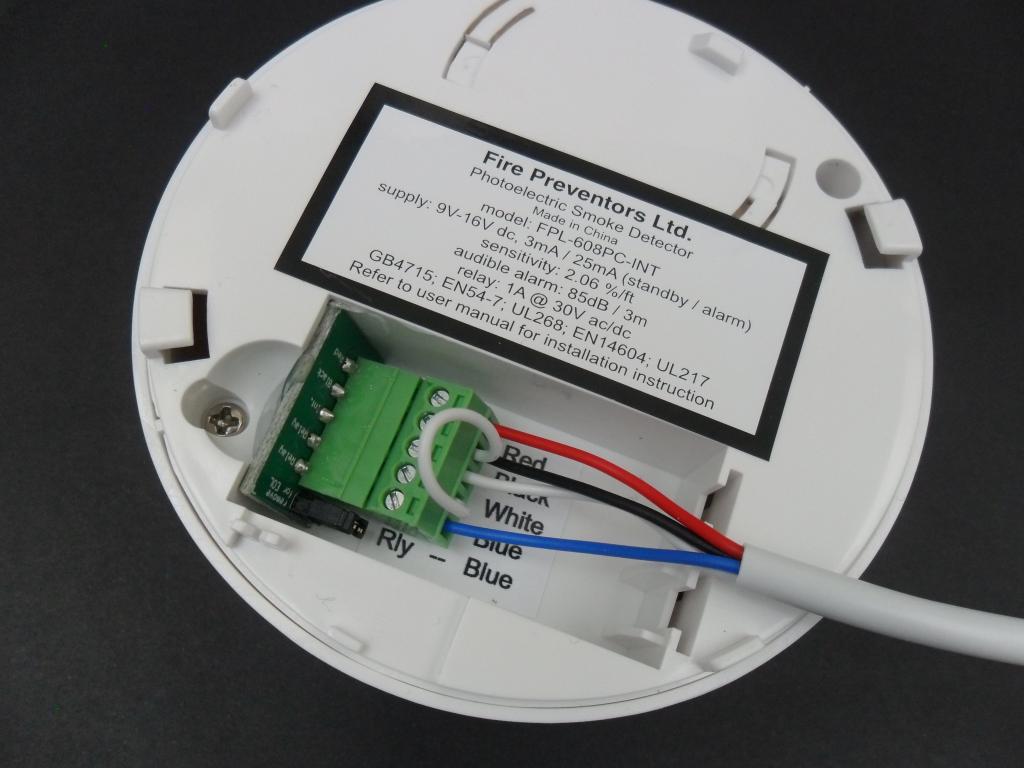
The red loop connection shown in the image is required for the Controller to trigger the smoke detector audible alarms.
The white 4-core wire to the right connects to the smoke detectors, the other wire to the flashing alerters.
After all terminations for the full system are complete, connect the backup battery to The Fire Denyer Controller. The green light. Mains power can be turned on.
The Load Fuse
This is a 2Amp fuse that protects the load. If this fuse is blown, there is likely a short on the wiring to the contactor or a faulty contactor. Replace with a normal-blow 2 Amp 5x20mm glass fuse.
Fire Denyer LED Indicator
|
LED Indication |
Meaning |
|---|---|
|
Green – |
Normal operation, mains power on |
|
Green – one minute brief pulse |
Normal operation, no mains power |
|
Red –
|
Smoke activation or Test Button pressed. Continues fast flashing until hushed (slow flashing) and then reset (green) System ‘hushed’. Hush effective for 3 minutes |
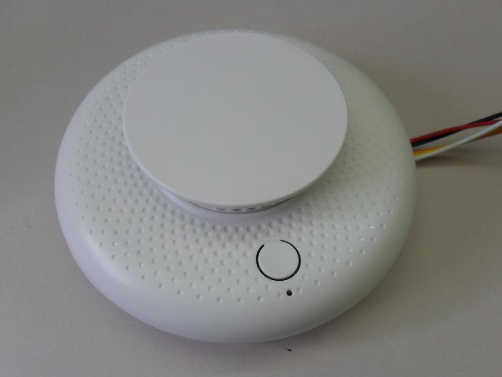
Smoke DetectorsFrom early December 2023 there is a new Smoke Detector.
This smoke detector is functionally the same but has a different connection method. A smaller wiring lead replaces the earlier green screw terminal block. The supplied wiring lead must be connected to the installed wiring using crimp joint caps. This is the recommended method for best reliability and service life. There are two wiring arrangements, one for a mid-line smoke detector and one for the End-Of-Line smoke detector. Wiring Diagram
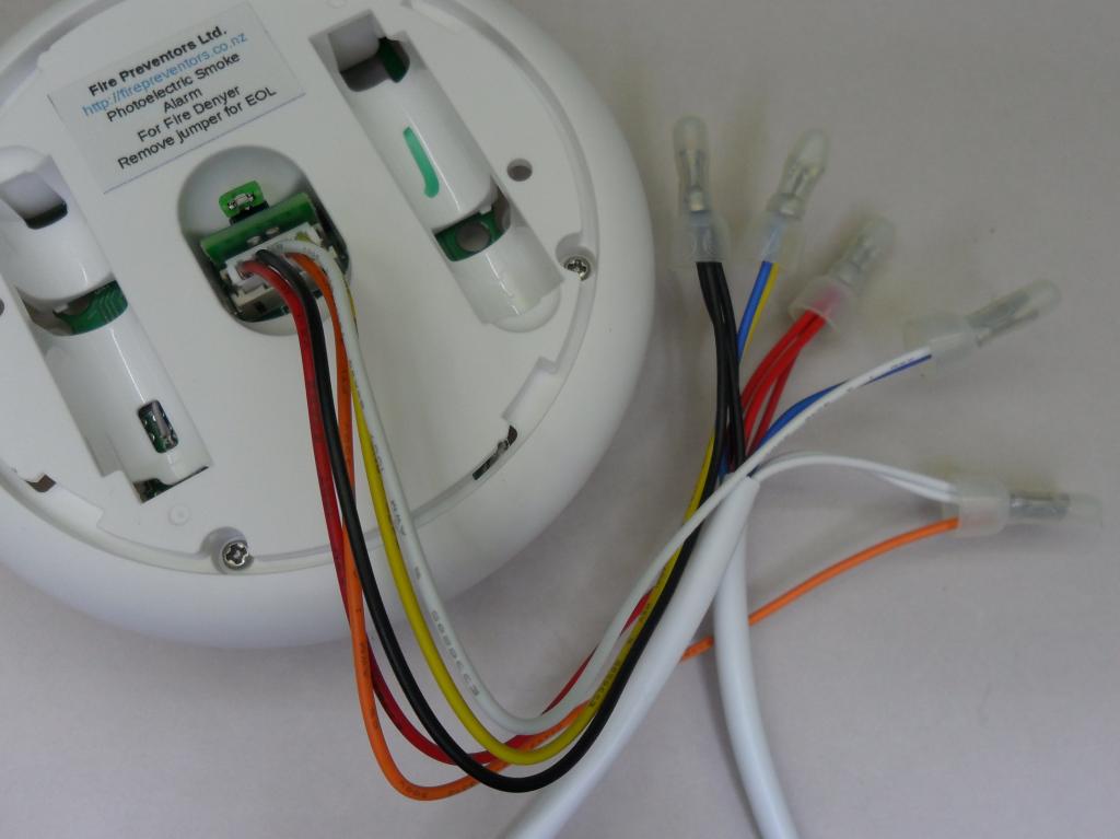
White cores are shown as green – easier than trying to make white show on a white background. Other colors are as shown. The crimp junctions caps are closed end crimp caps. Twist wires and fold if necessary before crimping. An indenting crimp tool is recommended for security – so they don’t fall off. Crimp junctions caps may be supplied with smoke detectors if available. The installer may be required to supply crimp joints. Mid-Line Smoke Detector
The orange wire from the smoke detector allows the Fire Denyer Controller to trigger the alarm withing the smoke detector. This is an output from the Controller, usually on the white core of the installed wiring. The white and yellow wires from the smoke detector are the relay output signalling a smoke detection back to the Fire Denyer Controller, usually on the blue core of the installed wiring. End-Of-Line Smoke Detector
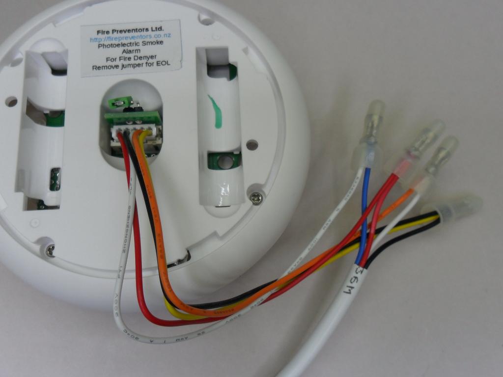
Remember to remove the jumper on the back of the smoke detector on this last smoke detector on the circuit. The detector trigger circuit, usually the blue wire, to the Fire Denyer Controller passes through the smoke detector relay and connects to the common power supply line, the black wire. . Original – older model Smoke Detector – for reference only
The white-core links the smoke alarm alarms and allows the Fire Denyer Controller to trigger the audible alarms in all smoke alarm. The blue-core is the smoke alarm output trigger circuit back to the Fire Denyer Controller. The image shows the last detector in the circuit with a wire loop installed. NOTE: the jumper has not been removed – a trap for young players. The use of different smoke detectors is not recommended. The use of 4-core 0.5mm security cable is recommended as it is readily available, reasonably priced, robust and generally has a mains rated sheath – Note that the cores are not mains rated. |
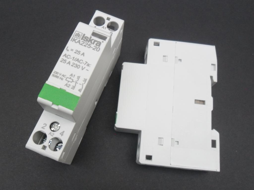
Contactor
|
Flashing Alerters
This image shows the blue-core which triggers the red flashing from the Fire Denyer Controller, and the white-core used to loop the door-bell button to the other Flashing Alerters on the circuit. The white wire is not connected at the Fire Denyer Controller. The bed-shaker is the twin black wire. If installed a battery must be plugged into the Flashing Alerter. |
| . |
Waking Vibrator or Bed Shaker
Wiring can be twin Tru-rip 0.5mm cable or the same 4-core security cable. The Flashing Alerter driving the Bed Shaker must have a back-up battery connected. The back-up battery pack is installed at the Flashing Alerter to ensure enough current is available to reliably operate the Bed Shaker. |
Door BellThe door bell switch is wired from any Flashing Alerter using twin Trurip 0.5mm cable. If a sounder is fitted for the door ‘bell’, it is powered from a Flashing Alerter. |
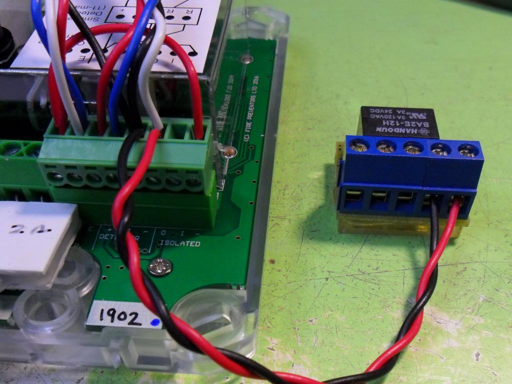
Auxiliary Relay – for remote monitoring
The relay -ve is connected to -ve (terminal 5 from the left) and the relay +ve to the output (terminal 6 from the left). When alarm activated, the controller switches +ve (nominal 12V) to the relay. Note: the output (terminal 6 from the left) also connects to the smoke detector interconnect wire, which triggers the smoke alarms on test or activation. The relay shown is a low current 12V relay providing a SPDT changeover contact. This relay includes a LED indication and draws approximately 15mA when activated. |
Triggering The FD Controller From Another SystemIt is important to electrically isolate the two systems using a relay or optically coupled interconnect (optocoupler). The isolation voltage must be at least “mains rated” – 230VAC here in New Zealand. The best option is to have the other system mimic a smoke alarm activation to the Fire Denyer. The other system opens a relay contact that appears to the Fire Denyer Controller to be a smoke alarm activation. If there are no smoke alarms installed you will need a 4.7K eol (end of line) resistor in series with the input on the Fire Denyer Controller. |
Installation Check ListAfter installation is complete, an examination of the system as a whole should be undertaken. The tests and checks are laid out in the Installation Check List on page 4 of the User Manual & Installation Guide (see web page ‘User Manual). The installer should initial the Check List. |


Notes – Testing
- When triggered by a smoke detector or the test button, the Fire Denyer Controller delays 10 seconds before triggering all of the smoke alarms. This makes it easier to locate faulty smoke detectors by easily identifying the one that alarms first.
Typical Installation Problems
| Contactor not working |
|