Installation Notes
- Use the correct tools – especially screwdrivers. Damage can result from using screwdrivers that are too big and when terminals are over tightened.
- Use the correct stranded cable for low voltage wiring. Typically 0.4-0.5 square-mm security cable.
- Strip the correct length and twist the strands before inserting wires into terminals.
- The Fire Denyer Controller is usually best installed near the kitchen light switch or somewhere handy for convenient operation.
- A standard single gang flush box will house The Fire Denyer Controller. The backup battery sits on a dwang near the flush box.
- Power supply to The Fire Denyer can be fed from a light switch, but it is best connected to its own supply on the switchboard before RCD supply, maximum 16 amps.
- A smoke detector is usually installed just outside the kitchen area. Additional smoke detectors are installed in all other areas considered at risk, for example bedrooms, lounge and laundry.
- Heat detectors can be connected if required and would normally be placed closer to the cooking appliance. Note: Heat Detectors will only detect an established fire, defeating the purpose of the Fire Denyer.
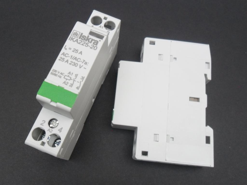
- The contactor requires two spaces on the switchboard. If there is no space available it may be housed adjacent to the switchboard in a suitable enclosure.
- Follow the wiring diagram for correct installation. Incorrect wiring may cause damage to the equipment.
|
Downloads – References
to come – maybe |
|
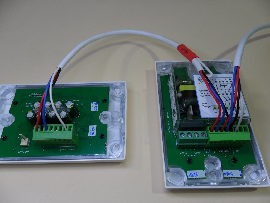
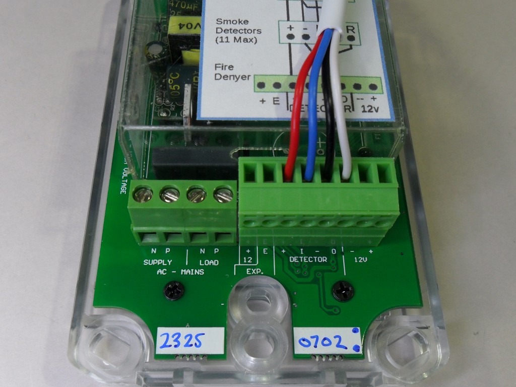
 Connections are shown in the small wiring diagram on the back of the controller. Connections are shown in the small wiring diagram on the back of the controller.
Low voltage wiring connects to the smoke detectors and Flashing Alerters (if installed).
The red loop connection is not required with this model and must not be fitted.
After all terminations for the full system are complete, connect the backup battery to The Fire Denyer Controller. The front green LED lights. Mains power can be turned on.
The 4-core wiring shown is 0.5mm security cable.
The mains power 4-pole screw terminals:
- Supply N = mains supply
- Supply P = mains supply
- Load N = switched supply to contactor
- Load P = switched supply to contactor
The 8-pole low voltage screw terminals:
- +12 = power, 12V DC always on
- E = trigger signal to flashing alerters – Blue Wire
- + = power, 12V to smoke alarms – switched off when hushed
- I = trigger signal from smoke alarms – 4K7 end of line resistor to seal/reset
- – = 0V gnd. common for smoke alarms and flashing alerters
- O = output trigger to smoke alarms – switches +ve to sound alarms
- – 12V = aux-power, 0V gnd, always on – generally not used
- +12V = aux-power, 12V gnd, always on – generally not used
. |
Fire Denyer Controller Battery
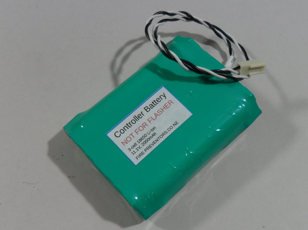
This is a 3-cell 18650 rechargable pack with internal battery management circuit.
It is charged slowly by the controller and runs the system when mains power is off.
This battery is mounted with the controller, generally behind the controller or in an adjacent flush-box. |
|
The power supply to protected circuits is interrupted by a contactor at the switchboard. Range, hob and kitchen power circuits are primarily protected. Clothes dryer, power and special function circuits can also be switched. Additional contactors, to cover more circuits, may be connected if required. The contactor is connected to the Fire Denyer Controller using TPS mains cable as shown in the wiring diagram. |
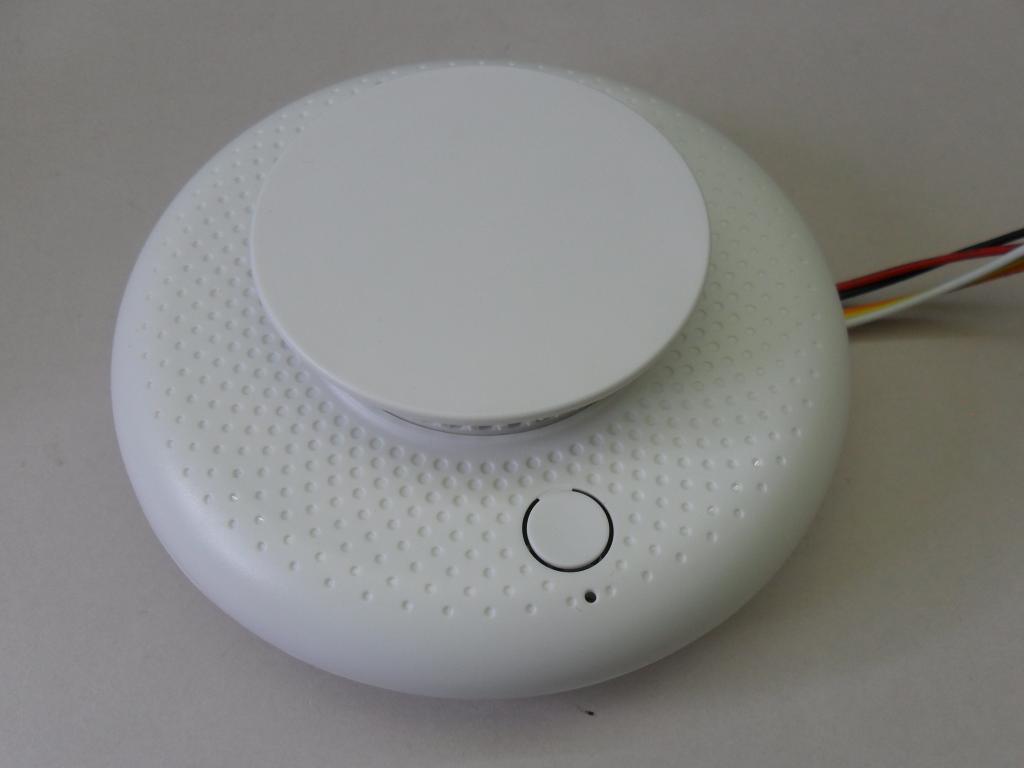
Smoke Alarm (smoke detector)
From early December 2023 there is a new Smoke Detector.
Due to the manufacturer discontinuing the earlier smoke detector this new model is now being supplied.
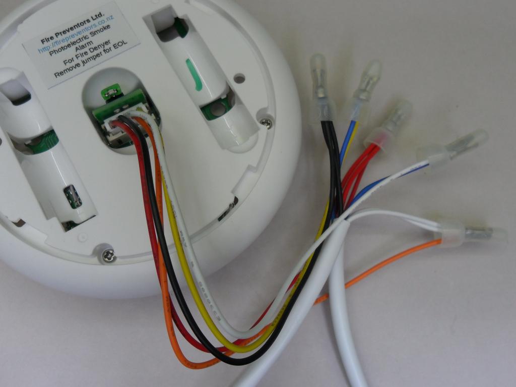
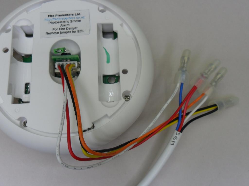
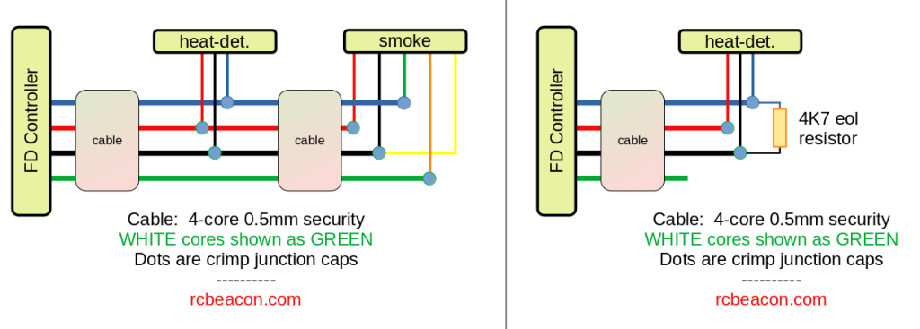
This smoke detector is functionally the same but has a different connection method. A smaller wiring lead replaces the earlier green screw terminal block. The supplied wiring lead must be connected to the installed wiring using crimp joint caps. This is the recommended method for best reliability and service life. There are two wiring arrangements, one for a mid-line smoke detector and one for the End-Of-Line smoke detector.
.
Wiring Diagram
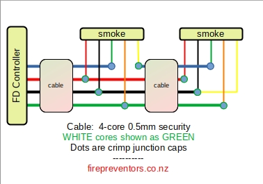
Using 4-core security cable, 0.5mm (0.44 is common). Conductors are black, red, white and blue.
White cores are shown as green – easier than trying to make white show on a white background. Other colors are as shown.
The crimp junctions caps are closed end crimp caps. Twist wires and fold if necessary before crimping. An indenting crimp tool is recommended for security – so they don’t fall off.
Crimp junctions caps are supplied with smoke detectors.
Mid-Line Smoke Detector
The detector trigger circuit, usually the blue core of the installed wiring to the Fire Denyer Controller passes through the smoke detector relay and on to the next smoke detector in the circuit.
The orange wire from the smoke detector allows the Fire Denyer Controller to trigger the alarm withing the smoke detector. This is an output from the Controller, usually on the white core of the installed wiring. The white and yellow wires from the smoke detector are the relay output signalling a smoke detection back to the Fire Denyer Controller, usually on the blue core of the installed wiring.
.
End-Of-Line Smoke Detector
Very similar to the mid-line wiring except that the alarm circuit of the last detector connects to the common power supply black core of the installed wiring.
Remember to remove the jumper on the back of the smoke detector on this last smoke detector on the circuit.
The detector trigger circuit, usually the blue wire, to the Fire Denyer Controller passes through the smoke detector relay and connects to the common power supply line, the black wire.
. |
|
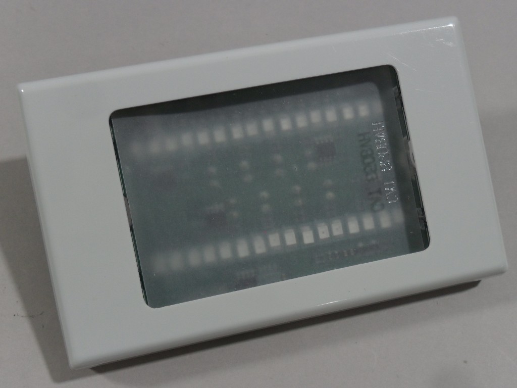
Flashing Alerters are wired back to The Fire Denyer Controller in a daisy-chain using 4-core 0.5mm security cable. Wiring is shown in the wiring diagram – some more detail in Technical Specifications.
Wiring is the same as the earlier model shown below.
The blue-core which triggers the red flashing from the Fire Denyer Controller, and the white-core used to loop the door-bell button to the other Flashing Alerters on the circuit. The white wire is not connected at the Fire Denyer Controller.
The bed-shaker is the twin black wire. If a bed shaker is installed, a flasher battery must be plugged into the Flashing Alerter.
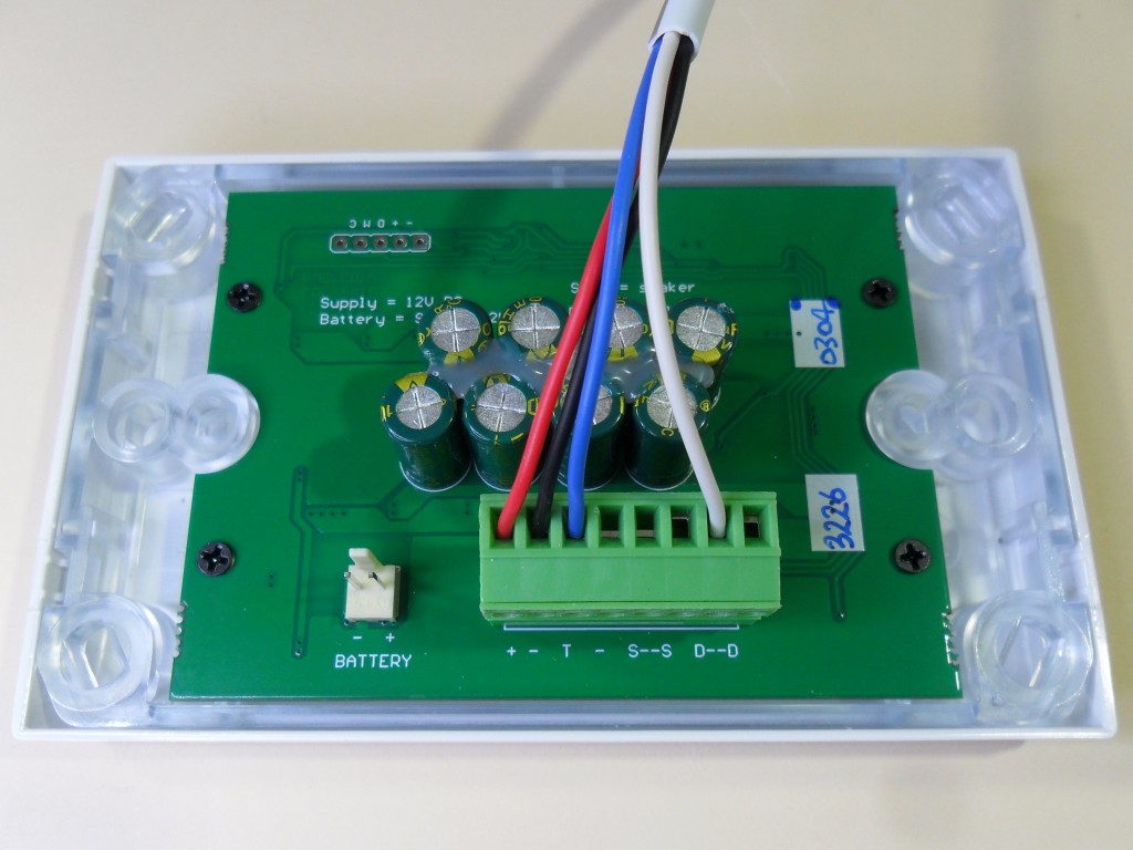
Controller wiring for flashers
This shows the controller wired for the smoke alarms, the 4-core cable on the right and the flashers (1 or more), the 4-core cable on the left.
- D–D : terminals connect the Bed Shaker. polarity doesn’t matter.
- S–S : terminals connect the Door Bell push button.
The 4-core wiring loops from the Controller between the Flashers :
- Red = +12V nominal
- Black = 0V, gnd.
- Blue = trigger wire from controller – pulls low to trigger
- White = door bell link – connects the door bell button to the flasher/s
. |
|
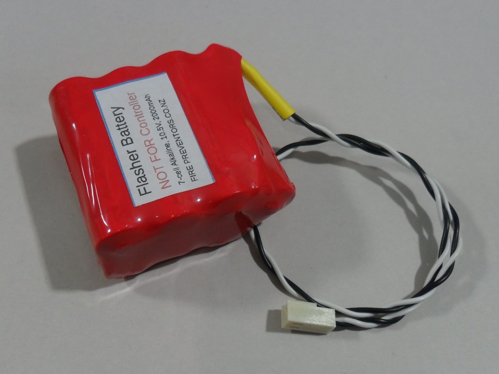
The flasher battery is only installed on a flasher that is driving a bed shaker.
During normal operation, the flasher battery is not much used – very low load.
For safety reasons this battery is alkaline based and not rechargable.
This battery should not be used on the controller.
. |
|
The Waking Vibrator is wired from a Flashing Alerter.
Wiring can be twin Tru-rip 0.5mm cable or the same 4-core security cable.
The Flashing Alerter driving the Bed Shaker must have a flasher battery connected. The back-up battery pack is installed at the Flashing Alerter to ensure enough current is available to reliably operate the Bed Shaker.
The bed shaker is not polarity sensitive. |
|
The door bell switch is wired from any Flashing Alerter using security cable or twin Trurip. If a sounder is fitted for the door ‘bell’, 4-core security cable is required. It is powered from a Flashing Alerter.
Any clean contact door bell button that does not include a light can be used.
Multiple buttons can be connected, say front and back doors. The flasher door bell function is linked between flashers via the white wire. This allows buttons to be connected to different flashers.
An audio sounder can be connected to any of the flashers. A 12V buzzer or piezo can be connected to the bed shaker terminals (D–D). |
|
NOTE: The heat detector will detect established fires, not the smoke present before a fire is established. This is a backup but defeats the original purpose of the Fire Denyer.
Detects high temperature and rate-of-rise. Suited to areas that may be smokey or dusty.
NOTE: The Heat detector does not include an alarm siren. If using the heat detector without smoke alarms on the system another audible alarm will be required. Contact us for options.
Multiple heat detectors can be combined with smoke alarms connected to the Fire Denyer Controller. The heat detector connects to the 12V power and zone trigger (blue) wires of the smoke alarm circuit.
Alarm point is approximately 57-degC.
When the heat detector activates, LEDs on the detector triggered glow and the Fire Denyer alarms. Reset using the Hush the Reset on the Fire Denyer Controller.
Installation – Wiring
The heat detector can be the only detector on the system which requires the 4K7 (4.7K or 4700 ohm) end of line resistor.
Recommended: The heat detector can be installed with smoke alarms in which case the last smoke alarm on the circuit provides the end-of-line resistor. |
Auxiliary Relay – for remote monitoring
A small (low current) relay can be connected as shown in the image to provide a clean-contact output for connection to monitoring or another alarm system.
The relay -ve is connected to -ve (terminal 7 from the left) and the relay +ve to the output (terminal 6 from the left).
When alarm activated, the controller switches +ve (nominal 12V) to the relay.
Note: the output (terminal 6 from the left) also connects to the smoke detector interconnect wire, which triggers the smoke alarms on test or activation.
Note: there is a 10-second delay from trigger to relay operation.
The relay shown is a low current 12V relay providing a SPDT changeover contact. This relay includes a LED indication and draws approximately 15mA when activated. |
Triggering From Another System
It is important to electrically isolate the two systems using a relay or optically coupled interconnect (optocoupler). The isolation voltage must be at least “mains rated” – 230VAC here in New Zealand.
The best option is to have the other system mimic a smoke alarm activation to the Fire Denyer. The other system opens a relay contact that appears to the Fire Denyer Controller to be a smoke alarm activation.
If there are no smoke alarms installed you will need a 4.7K eol (end of line) resistor in series with the input on the Fire Denyer Controller. |
Possible Problems and Installation Testing
After installation is complete, an examination of the system as a whole should be undertaken.
- When triggered by a smoke detector or the test button, the Fire Denyer Controller delays 10 seconds before triggering all of the smoke alarms. This makes it easier to locate faulty smoke detectors by easily identifying the one that alarms first.
|
Earlier version parts – Reference only
Older Documentation
Wiring diagram – pdf: fire-denyer_system-wiring-diag_01-2015_2
Original Installation Manual – pdf: fire-denyer_manual_01-2015_2
Batteries
The original system used NiMh rechargable batteries for both controller and the flasher. Over the years Lithium batteries replaced NiMh which became very expensive and hard to get. Batteries are all classified as dangerous good for bulk shipping which complicates the crap out it and makes bulk shipping very expensive.
The Fire Denyer now (as of 2026) used an 18650 pack for the controller and an alkaline pack for the flasher – see details above.
Controller – before mid-2024 – for reference only
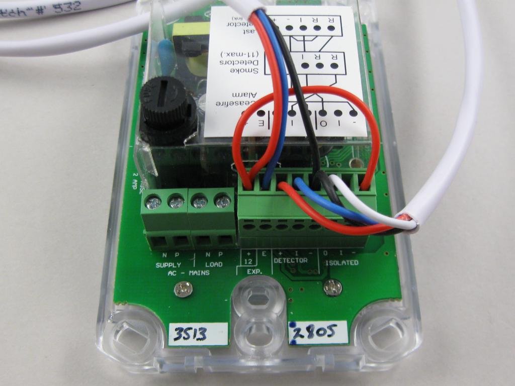
This model required a wire link between the two end terminals of the 8-way connector.
NOTE: the newer model does not use this wire link.
The much earlier model does not have the 2-Amp load fuse.
The white 4-core wire to the right connects to the smoke detectors, the other 4-core wire (white not used) is to the flashing alerters.
.
.
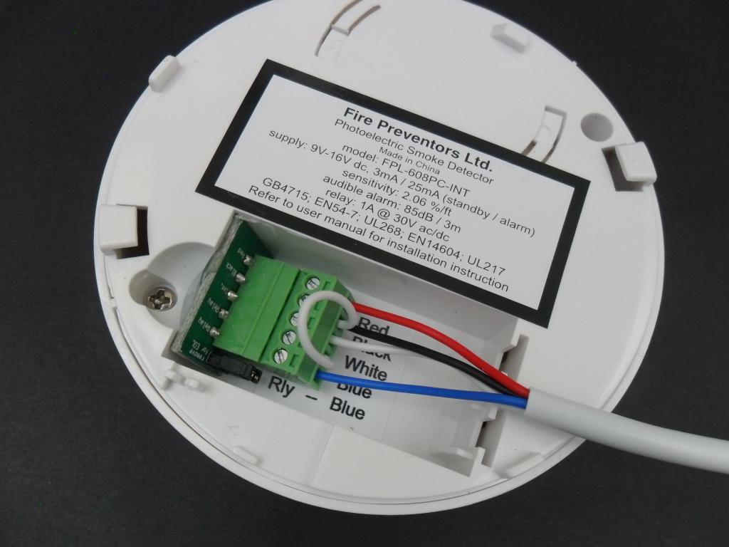
Smoke Detector – before December 2023 – for reference only
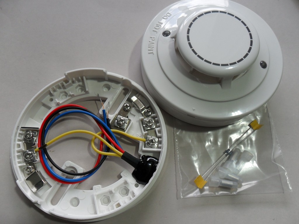
The 12V smoke detectors (smoke alarms) supplied are installed in the areas to be protected. The smoke alarms are wired back to The Fire Denyer Controller in a daisy-chain arrangement using 4-core 0.5mm security cable. A 4.7k End-of-Line Resistor is installed at the last smoke alarm only. See the wiring diagram.
The white-core links the smoke alarm alarms and allows the Fire Denyer Controller to trigger the audible alarms in all smoke alarm.
The blue-core is the smoke alarm output trigger circuit back to the Fire Denyer Controller. The image shows the last detector in the circuit with a wire loop installed. NOTE: the jumper has not been removed – a trap for young players.
The use of different smoke detectors is not recommended. The use of 4-core 0.5mm security cable is recommended as it is readily available, reasonably priced, robust and generally has a mains rated sheath – Note that the cores are not mains rated.
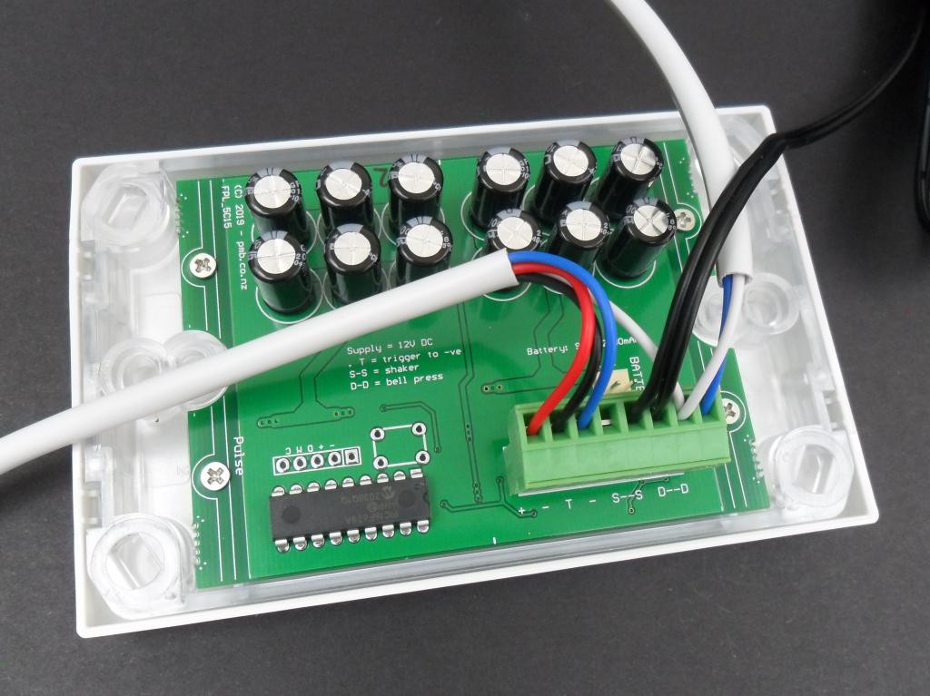
Flashing Alerter – before mid-2025 – for reference only
There have been several early version flashers. Mostly due to availability of suitable LEDs.
They are all functionally the same.
The picture (right) shows a black wire to the bed shaker and white/blue wire to the door bell button.
. |
Place Holder
Content |