Introduction
This is a page of general notes relating to the Hobbyking MINI MWC Flight Control Board with DSM2 Receiver ACC/GYRO/BARO/MAG.
This is supposedly a good FC. Not easy to set up, but possibly worth the effort if you want a small MultiWii board.
At first glance it’s not well documented or supported. You will need to understand Arduino and Multiwii. There are several manuals or guides on-line but they are very basic and don’t really help anyone new to Multiwii and this board.
There is now a V1.3 board but HK are still selling the V1.2. The only real advantage of the V1.3 that I can see is the higher precision barometer. There is also a difference with the GPS interface. It seems the GPS interface doesn’t work on the V1.2 board and requires a UART to I2C converter on the V1.3 board.
Initial Traps
In theory this board supports a GPS module for position hold and Return To Launch. But to connect the GPS you need a I2C-GPS adapter module that converts the TTL-UART of the GPS to I2C for the controller board. Check Ebay or Deal-Extreme for “I2C-GPS”.
I couldn’t find a schematic diagram for the Mini-MWC board. It is supposedly configuration compatible with the HK_MultiWii_SE_V2 board; so the schematic should be very similar. It includes a C8051F330 co-processor, but I don’t know exactly what this does. It likely converts UART to I2C for the GPS port connector and possibly has something to do with CPPM generation. But there’s no proven information yet and it may be doing nothing.
Getting Started
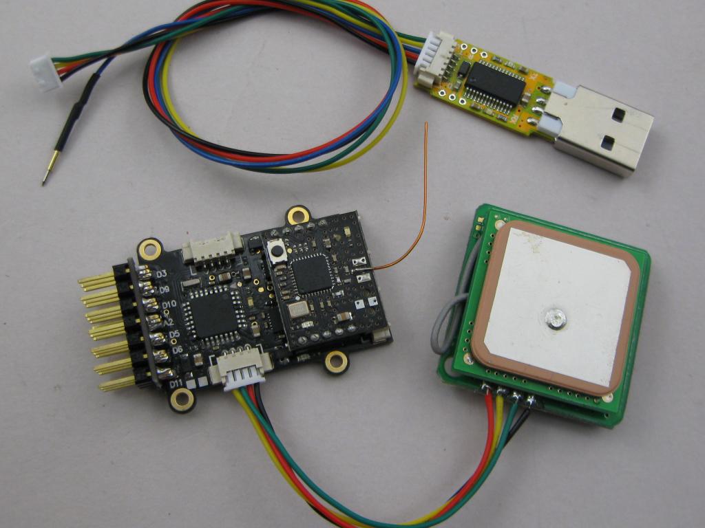 You need an Arduino interface to the Mini-MWC controller. Hobbyking sell a suitable FTDI programmer with the needed lead; here. The flying lead probe connection is needed to the Reset of the CPU to put the 328P in programming mode. This interface works for loading sketches to the Mini-MWC (with the reset probe) and with the Multiwii Conf utility (without the reset probe). The FTDI programmer will power the Mini-MWC.
To bind the DSM2 receiver with your tramsnitter: Power the board via the output headers – D3 to D11) while pushing the bind button (the one on the small receiver board). The red LED will flash rapidly and you are now in binding mode. Turn on your DSM2 compatible transmitter while pressing its bind button. The LED on the Mini MWC will stop flashing then will stay on. It is now bound to your transmitter. While RC connected (transmitter on or in range) the receiver board LED is on solid. When not connected, it is flashing.
Run the Arduino IDE and load the MultiWii shetch. Most configuration is done in the config.h file. Select the correct board by un-commenting #define HK_MultiWii_SE_V2. It is supposed to be fully compatible with the Mini MWC to set up the connections, sensors etc. Also un-comment #define SERIAL_SUM_PPM.
You can run both Arduino and Multiwii Conf programs at the same time, but only one can connect at a time. I’m using Linux, so this may not apply in Windows. Arduino releases the USB when it’s not using it. In Multiwii Conf, stop the connection and close the comm before loading a new sketch with Arduino.
Notes:
 You can disable the serial console (Multiwii Conf) by commenting out serialCom() in the file multiwii.cpp at about line 490. This would in theory allow the only UART to be used for GPS. But then how do you configure the rest of it? Enabling #define GPS_PROMINI_SERIAL allows auto-sense of GPS presence at reset. This allows switching between GPS and Multiwii Conf on the UART (port-0). This way, Multiwii Config does allow setup of GPS-Hold and RTL modes even though the GPS is not plugged in while the Conf program is connected.
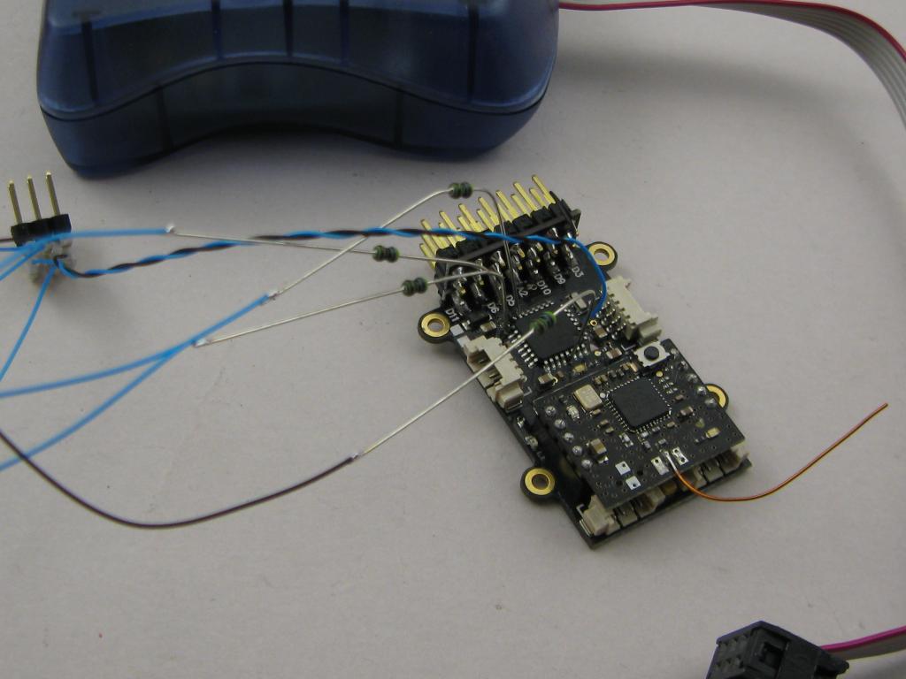
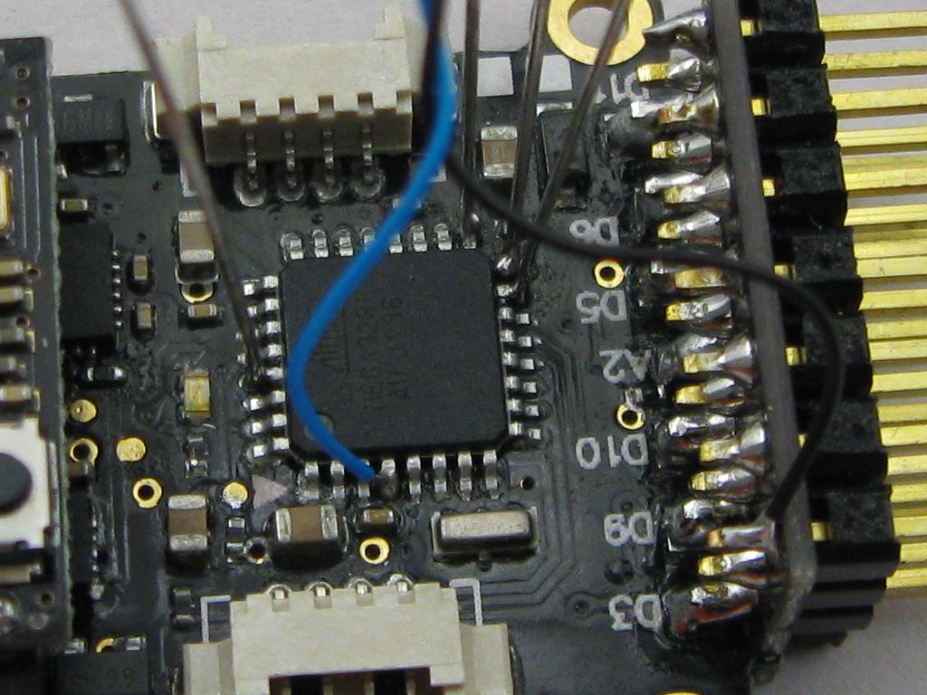
Be careful to stop and disable the port in Multiwii Conf before uploading a new sketch. I didn’t and managed to corrupt the Arduino bootloader. Without the adaptor, I had to solder to the Atmega328 and use the AVRICSP programmer. About 45 minutes to set up and 1 minute to reload. I used small resistors as stiff wire links to attach to the CPU. They are only 15 ohm; just what was on the bench.
The tricky part is how to tell the GPS is recognized after a reset. Maybe a “pilot lamp” would be useful. It connects to one output (D8), normally the buzzer and drives 3 LEDs and a buzzer. It uses pulse lengths from 100uS to 1mS (100uS steps) to control on/off of each.
Other Examples and Links
MultiWii Airplane Here. – sorry, this link died at the other end 04-May-2015.
Details from Hobbyking
From The Hobbyking product page Here.
- 7CH DSM2 Compatible Receiver (PPM SUM)
- Self-voltage checking
- FTD1 protection
- ATMEGA328P Microcontroller
- MPU6050 Accelerometer and Gyro
- BMP085 Digital Barometric Sensor
- HMC5883L Digital Manometer/Compass
- C8051F330 MCU CYRF69103 Radio
- Dual I2C Ports
- UART GPS Port (GPS not included)
- OLED Screen Port (OLED not included)
The following functions can be achieved:
- Auto stabilization
- Stabilize the altitude
- Fixed heading course
- Hovering at an identified position (needs 12C-GPS converter board and code support)
- Return flight automatically (needs 12C-GPS converter board and code support)
- And more
MINI MWC flight board supported modes:
- GIMBAL-individual cradle head stabilization
- SINGLECOPTER-VTOL single axis
- BICOPTER-BICOPTER Avatar
- Tricopter – FLYING WING
- VTAIL
- Fixed-wing airplane
- 4-Axis(QUADX,QUADP,Y4)
- cradle/gimbal head stabilization
- 6-Axis(Y6,HEX6,HEX6X)
Options not included: (Stock will be coming soon):
- MX-FTDI programming stick tool
- OLED screen, can be mounted on MINI MWC flight control board directly
- IIC to UART converter board, It is for changing the UART signal of GPS to a IIC signal
- GPS module
Specs:
- Weight: 7.8g
- Working voltage: 5-8.4V
Transmitter for MINI MWC flight control board needs to support DSM2 and 4CH or above (we recommend 6CH or above)
PRODUCT ID : 9154000006-0