Available for order – Here.
Introduction
 A fire protection device that will cut power to any connected equipment when the temperature rises too quickly or exceeds the maximum (approx 46 Deg-C).
Can be used to protect and alarm equipment cabinets, storage areas or anywhere with operating electrical equipment that could cause a fire – almost any electrical equipment.
Developed as a rate-of-rise temperature monitor, this device has it’s own temperature sensor, directly switches mains power, sounds an internal alarm and optionally triggers another system when triggered.
It can also monitor one or more additional smoke detectors or other sensors. A slave unit can be connected to trip other power circuits when triggered. This is useful when a UPS is used to trip the supply to the UPS and the output from the UPS.
Other applications
We can supply the unit configured to switch the output power on when tripped. This would be useful for controlling fans or pumps.
Using a moisture sensor rather than a smoke detector, the unit could switch off a pump and raise the alarm.
Industrial applications: Over-temperature detection and protection of motors and motor driven gear boxes.
Installation example – laser cutter
Install the temperature sensor in the exhaust air-flow path or duct. Somewhere where the air exiting the machine must pass. If a fire occurs within the machine the temperature of this air will rise. We can not detect smoke because the normal cutting process can produce smoke.
Plug it in and switch the power on. Wait the 45 second settling time, during which the unit will not trip.
Testing is explained below.
Note: the auxiliary alarm output contact can be used to activate a remote audible alarm and possibly also trigger a fire extinguisher within the laser cutter.
Installation – Computer cabinet
Install the temperature sensor near the top of the cabinet where it will sense rising hot air. A smoke detector can also be installed. Keep the smoke detector central, away from corners where there may be dead air.
Plug it in and switch the power on. Wait the 45 second settling time, during which the unit will not trip.
You will have to consider where the UPS (if used) fits into the picture. Switching power off to the UPS will not isolate the computer/s. Switching power off between the UPS and computers leaves the UPS running and possibly the cause of the heat or smoke. A lower cost slave unit can be used to switch the output side of the UPS off while the master handles the input side.
NOTE: switching the power off to computers can be problematic. Testing should be carried out by a suitably experienced person.
Testing is explained below
Testing
Initially, the unit should be tested for a period (maybe a week) by installing the temperature sensor and any additional sensors (smoke detectors etc.) and running the unit but not yet feeding/switching the power to the equipment to be protected. This will verify that normal temperature rate-of-rise and peak detection do not cause false tripping. If you have no trips during the test period, it is likely safe to switch the equipment over to the unit.
Holding the temperature sensor firmly in a warm hand should raise the temperature fast enough to cause a trip; assuming the ambient temperature is not too tropical to begin with. If your hand is not warm enough or the ambient temperature is high, you may need another heat source such as a hair dryer. Once the temperature of the sensor exceeds about 45 deg-C you will not be able to reset the unit until it reduces. So don’t get it too hot.
Testing from the sensor or smoke detector tests the full system and also kills power to the equipment.
Annual (yearly) testing is recommended. NOTE that this will trip power to the equipment.
It is possible to wire a remote test button to the temperature sensor. Contact PMB-NZ for details. This is not recommended as anyone pressing the button will cause a trip.
Operation
Plug it in and switch the power on. Wait the 45 second settling time, during which the unit will not trip. Connect the load and switch on.
During normal operation, the unit has no effect. When tripped, the power is cut off and the audible alarm pulses; like most smoke detectors. The auxiliary output contact also opens or closes (depending on configuration).
When tripped, the first press and releasing the reset-button will hush the audible alarm and reset the Aux. alarm output only. Press the reset button a second time to fully reset the unit and restore power. The button cannot be overridden to prevent tripping.
When tripped and silenced but not fully reset, the alarm can be re-triggered if the conditions are not yet restored, ie. temperature lowered or smoke cleared. This means you cannot hush it and ignore the problem or leave it for later.
Manually tripping the unit is possible by holding the reset button pressed for about 7 seconds.
Specifications
- Mains Supply: nominal 230V AC mains power 10 Amp maximum
- power usage: approx. 1 watt
- Load switching: 230V AC, 10 Amps Max.
- LED Indicator: ON + flicker = normal, Flashing = tripped
- Reset switch: press to hush, press again to reset
- Audible alarm: Piezo pulsed alarm
- Auxiliary output contact = 230V 10A rated = close on tripping
- Sensor = 10K NTC thermistor
- Detector input = 470R end-of-line
- Available with various power connector types (contact PMB-NZ)
.
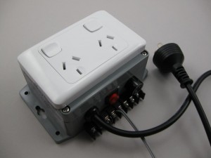
Connections
 There are six screw terminal on the unit. These are not connected to mains power internally and are safe to touch. NOTE: the auxiliary output terminals are rated to switch mains power externally; in which case all due care should be taken.
Connections Left to Right:
- +12V-DC
- smoke zone input
- 0V common
- Thermistor sensor (to 0V, 3)
- Auxiliary output relay
- Auxiliary output relay
Note: the very end screws secure the connector to the case – don’t remove these screws.
Sensors
The temperature sensor is a standard 1% 10K NTC thermistor. If replacements are required, we can supply them or you can obtain them from many of the larger electronic component suppliers.
Smoke detectors of other sensors can be connected to the “zone” input. This is a monitored line input that will trigger the unit when short-circuited or open-circuited. The EOL (end-of-line) resistor is 470 ohms 1%; readily available if spares needed. The EOL resistor should be installed at the last detector in the circuit to ensure the integrity of the wiring.
Danger Notice:
This unit contains HIGH VOLTAGE wiring and circuitry. Taking it apart or modifying it in any way may be dangerous.
Should the unit be damaged or become wet, Immediately disconnect it from the power supply before touching it.
Options
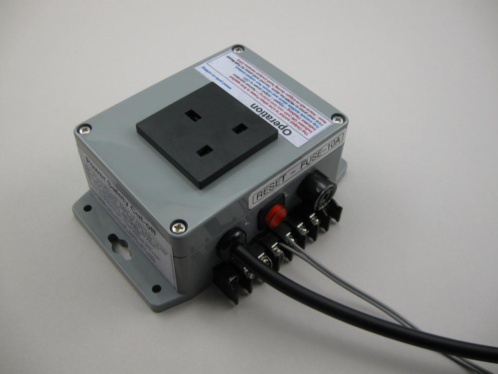
UK lead and socket
Power connectors for other countries can be fitted when requested.
This is a stand-alone unit pre-set for normal use. In some cases more or less sensitivity and/or a higher or lower maximum temperature may be desired. We can adjust these during assembly and testing.
We can also make the maximum temperature trip point a minimum temperature trip point or a window detection by specifying upper and lower limits. This could be useful to prevent equipment from being re-started if the temperature is too low.
Slave Switched Outlet
This is a unit that looks like the main Fire Cutoff unit but is simply an auxiliary mains power switch. This can be used to control isolated supplies such as outputs from a UPS.
This function requires the auxiliary output relay.
Ordering and Product Status
Current – Available for order. – please use the contact form for inquiries.
1-2 units in stock at any time. Produced as required meaning a lead time of approximately one week from order.
I welcome comments or questions. Feel free to comment below or use the Forum.