Note: This describes the hardware and does not account for any code or logic running on the esp32.
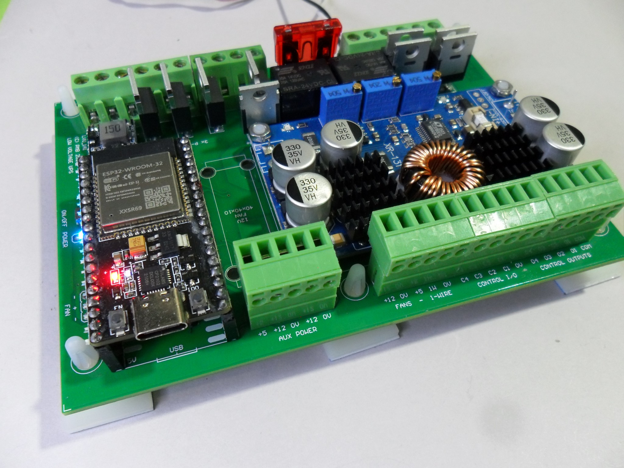
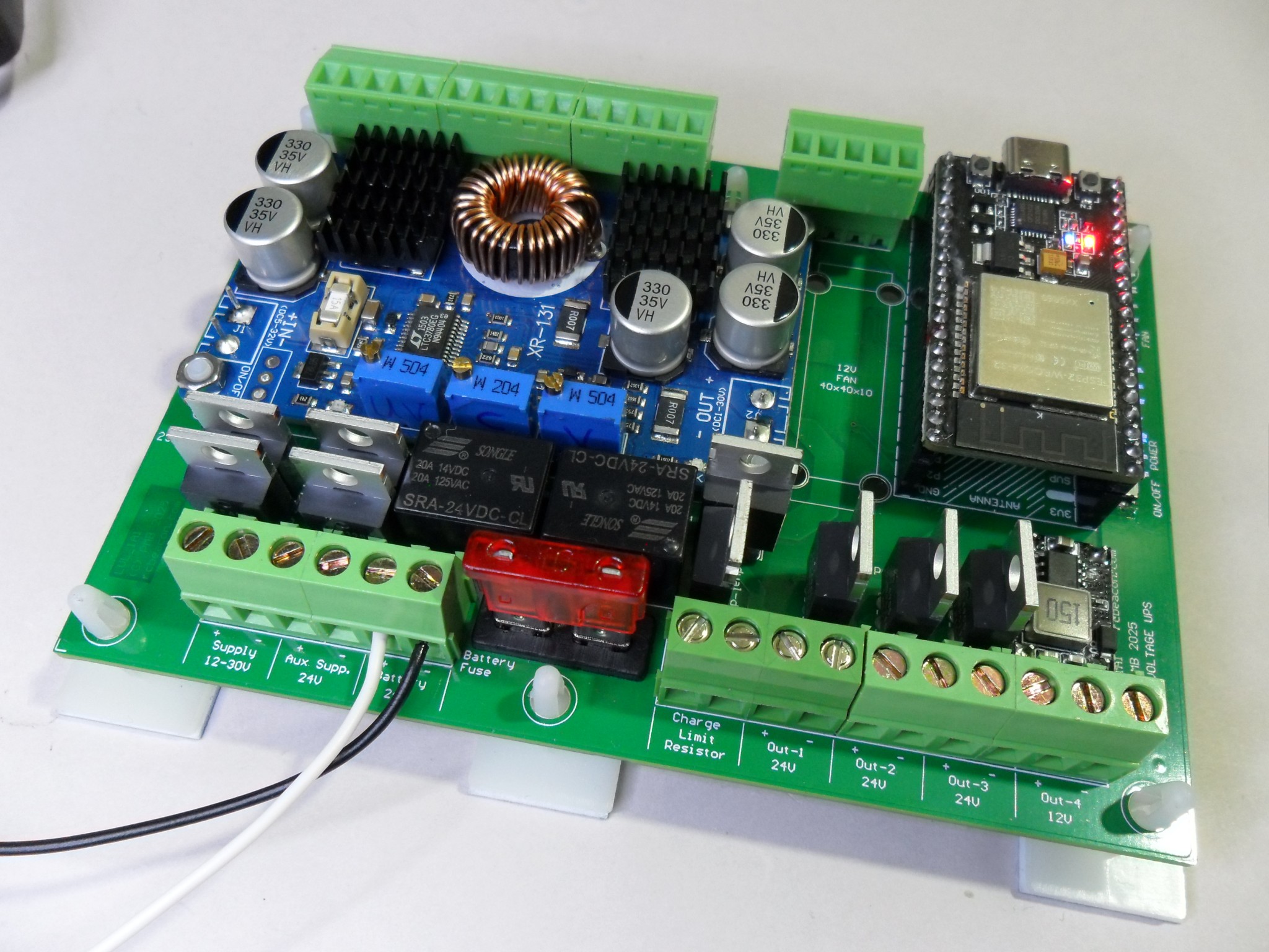 This is a 24V UPS module supporting a 24V battery to power a NAS motherboard and hard drives. Control and monitoring provided by a NodeMCU esp32 module. Originally designed for a NAS of a Odroid H2 motherboard and 3.5″ hard drives.
The module takes 12 to 30 VDC in to charge a 24V battery. Then provides several 24V and 12V output supplies that can be switched. A few I/O control connections can monitor and control the motherboard for managed shutdown on power loss or low battery. The module can be adjusted to support a 24V SLA or 6-cell 18650 lithium battery.
How it works:
On-board is a 24VDC bus which is usually at the battery voltage – 27.6Vmax for SLA or 25.6Vmax for 18650. The incoming main supply passes through a boost/buck regulator which sets the bus (and battery-maximum voltage). Supply outputs are switched out from the bus. Three 24V outputs and a lower current 12V output. The esp32 is powered from the battery and can be put to sleep but cannot be powered off if a battery is connected.
The Aux Supply input must be regulated to suit the battery-max voltage. This could be from a solar regulator.
Making it go:
 The battery must be connected first to power the esp32 module which then has control over incoming supply and output supplies. To make anything else work the “battery discharge” relay must be activated. The main outputs and Aux 12V outputs can then be controlled.
Other control I/O is a function of code running on the esp32. This could be simple on/off control or include controlled start-up/shutdown and battery state testing by controlled runs from battery with the main supply as backup. A 1-wire circuit supports temperature sensors (potentially other I/O) allowing fan control to maintain cabinet temperature.
Battery connection and Notes:
Do not reverse the battery connection: As it must support charging and discharge, there is no reverse polarity protection and you will most likely destroy it. If polarity protection is required, I recommend a fuse and really big diode across the supply between the board and the battery.
There is a battery fuse on-board which is for overload or major failure protection.
The battery operates in float or standby. If a 24V SLA battery is used the boost/buck module is set to supply a maximum of 27.6V to the battery to prevent over-charging. For a 6-cell 18650 battery the voltage is set to 25.2V and the battery must have an internal BMS for safety.
Battery Charging:
When charging the current must be limited to protect the module, battery and ensure the load power is reliable. At the start of charge the battery state is not known and a flat battery may try to draw a lot more current. As the battery type and size is not known an external current limit must be connected. A good option is probably a small incandescent lamp – a 12V or 24V, 10-20 watt automotive lamp. This will allow higher charging currents as the battery voltage rises but protect everything if the battery voltage is low. Be aware that a shorted or partially failed battery may have the lamp glowing and hot for some time.
The could also be a power resistor sized to limit the charge current to 1-2 amps at 5-10 volts. Smarter options are also possible but probably more complex than necessary.
An external charger could be connected directly to the battery if required. The voltage must bot exceed 28 Volts.
GPIO Notes:
.
| Board Function | esp32 GPIO number | Notes | More Notes |
| Aux. Input Voltage | GPIO34 ADC6 – analog | 100K-10K voltage divider | |
| Supply Input Voltage | GPIO35 ADC7 – analog | 100K-10K voltage divider | |
| Bus Voltage | GPIO36 ADC0 – analog | 100K-10K voltage divider | |
| Battery Voltage | GPIO39 ADC3 – analog | 100K-10K voltage divider | |
| Control I/O 4 | GPIO02 (esp32 module LED) | General purpose control I/O – Floating – do not pull-up – recommend use as output | Strapping: at boot selects flash voltage – avoid pull up/dn at boot |
| Control I/O 2 | GPIO04 | General purpose control I/O – with pull-up | on-board “power on/off” LED |
| Control I/O 3 | GPIO05 | General purpose control I/O – with pull-up | |
| Opto Control Output 4 | GPIO12 | Isolated open collector output | Strapping: flash voltage select – must be low at boot for normal 3.3V operation |
| 1-Wire Sensor | GPIO13 | DS18x20 temperature sensor/s | |
| Opto Control Output 1 | GPIO14 | Isolated open collector output – CPU power button | |
| External Fans | GPIO15 | External cooling fan/s | Strapping: boot device select – float/low at boot |
| Control I/O 1 | GPIO16 | General purpose control I/O – with pull-up |
Strapping: safe on esp32 (wake from deep sleep on esp8266). on-board on/off button |
| Opto Control Output 2 | GPIO17 | Isolated open collector output – CPU reset button | |
| Battery Discharge on/off | GPIO18 | Connects battery to Bus | |
| Onboard Fan | GPIO19 | Board cooling fan – if fitted | |
| Main Supply on/off | GPIO21 | Main 12-30V DC supply | |
| Aux Supply on/off | GPIO22 | Secondary battery | |
| Battery Charge on/off | GPIO23 | Connects Bus to battery via charge current limit resistor | |
| Output 1, 24V on/off | GPIO25 | Main load power – NAS CPU | |
| Aux 12V on/off | GPIO26 | 12V for on-board and off-board Aux functions | |
| Opto Control Output 3 | GPIO27 | Isolated open collector output | |
| Output 3, 24V on/off | GPIO32 | Main load power – HDDs | |
| Output 2, 24V on/off | GPIO33 | Main load power – HDDs | |
ESP32 Setup using Tasmota32:
AdcGpio34 0,4095,0,36.5 ; configure ADC to show voltage with 10K-100K divider
AdcGpio35 0,4095,0,36.5 ; 0-4095 ADC count- translates to – 0-36.5V
AdcGpio36 0,4095,0,36.5 ;
AdcGpio39 0,4095,0,36.5 ;
Tasmota Template String:
{“NAME”:”NAS-Controller-1″,”GPIO”:[1,1,1,1,1,1,0,0,234,1312,237,233,1,236,224,232,0,227,228,225,0,229,226,235,0,0,0,0,231,230,11264,11265,11266,0,0,11267],”FLAG”:0,”BASE”:1}
.