Open LRS Transmitter
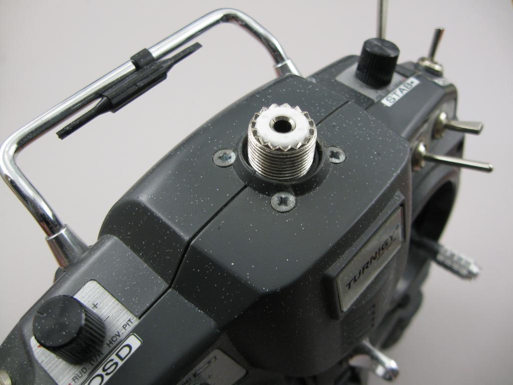
It didn’t matter and there was little danger as the telemetry-beeper indicated a fault before it became a problem. Having some time ago modified the Turnigy 9X transmitter to include a PL259 antenna socket in place of the original telescopic antenna, I decided to fit the PC Board from the OpenLRS module inside the radio rather than plugging it in the back of the transmitter. This allows the module to take advantage of the PL259 connector and accept a variety of antennas. Using a OpenLRS receiver as a transmitter was one option, but I decided to strip the module and clean up and install the PCB. This was simpler as the transmitter already had buzzer driver LEDs and a reasonable voltage regulator on-board.
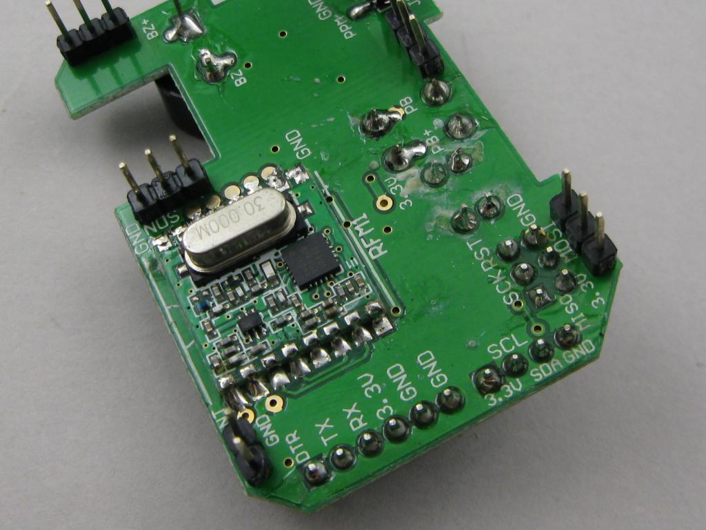
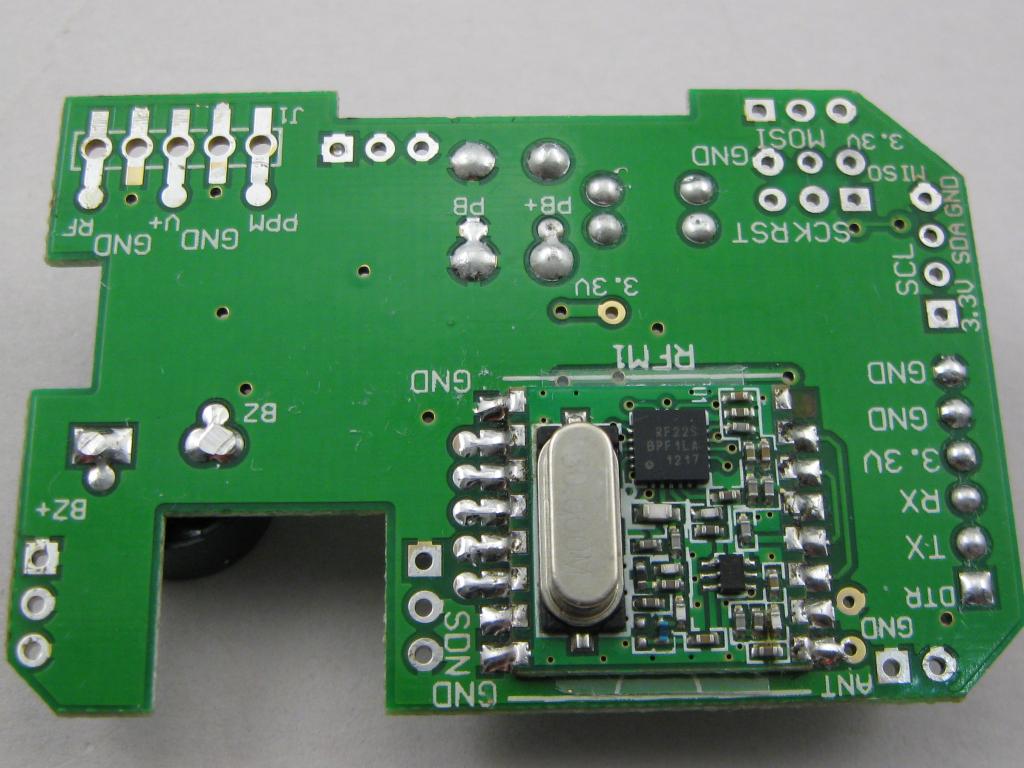
Without looking at the data I think this is one or the T/R select control lines. There must have been some connection or the default state was OK, because it had been working. The HopeRF module was mounted up on a silicon pad and using large untidy solder blobs to secure and connect it. I replaced the thicker silicon with a thin mylar sheet. |
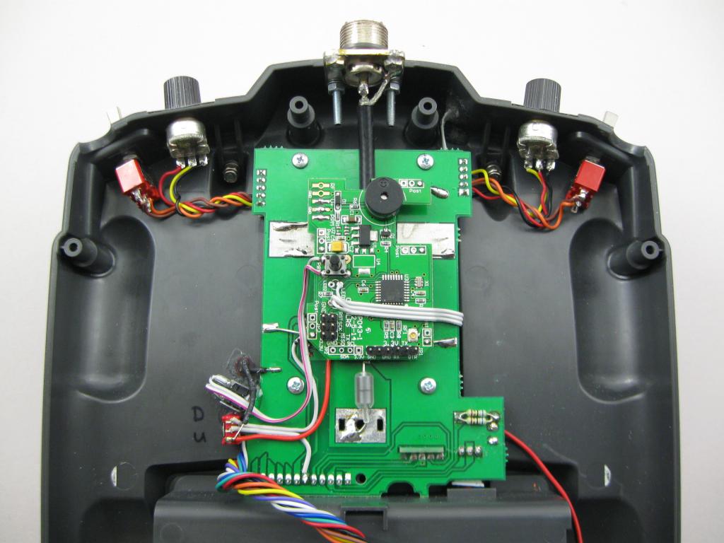
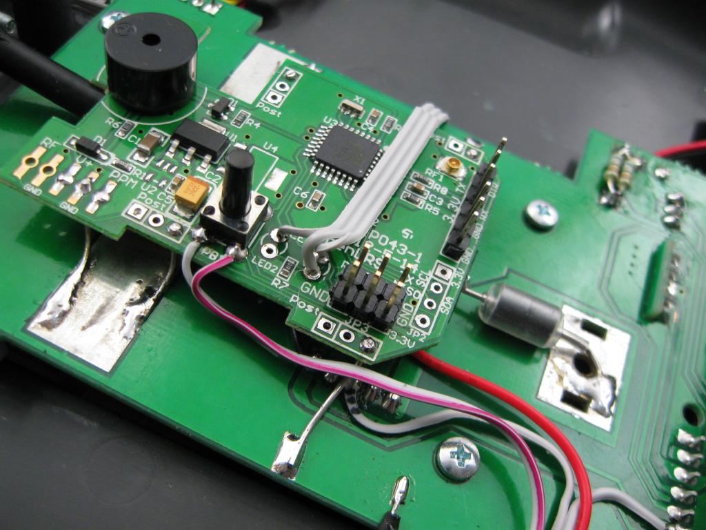
Installed into the Turnigy 9X
The antenna coax centre core passes through a couple of beads and still attaches to the original board. This allows the 35MHz JR module to still be used. The 433MHz module should withstand the 35MHz signal on its antenna connection without damage. The LEDs and push button are wired to an external dual-colour LED and a recessed mini push button for binding etc.
|
The Finished Radio
At 433MHz it’s best to keep any coax extensions as short as possible. BTW: The white speckles on the radio are due to over-spray when I was painting something else and left the radio in the garage within range. It adds character. |
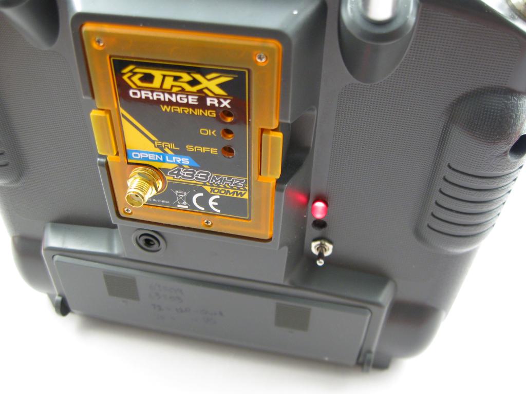
The Back Panel
The LED indicates when the internal OpenLRS module is enabled The Orange module is now empty and just fills the hole. |
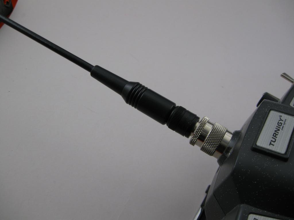
Antennas
There are various antennas available for 433MHz (the HAM 70cm band) with PL250 and BNC connectors. Some of these require a ground plane, and some not so much. Almost anything will be much better than the little 75mm rubber duckie supplied with the OpenLRS modules. The rubber duckie antennas look exactly like 2.4G wifi antennas but have a single spring-whip of about 50mm length inside. |
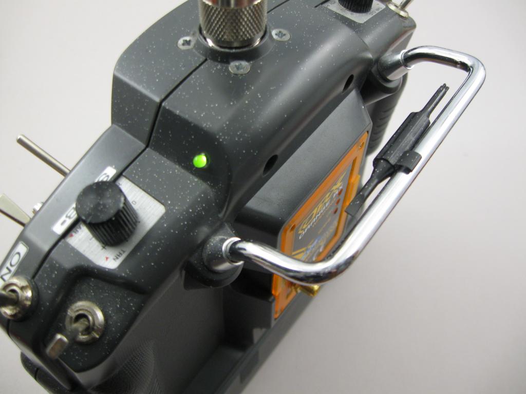 This is the dual-colour (red/green) LED that replaces the red and blue LEDs that were on the OpenLRS module. This is the dual-colour (red/green) LED that replaces the red and blue LEDs that were on the OpenLRS module. |
Open LRS Firmware UpdatesAt the moment I still have to take the back cover off the transmitter to update the firmware. One option would be to add a small selector switch and connect it to the FTDI board that is already installed. Switching the RXD and TXD would be easy. It may also be handy to allow the switching to connect the OpenLRS module and the 9X processor so that telemetry data can be displayed on the LCD. Maybe later on. |
| . |