Introduction
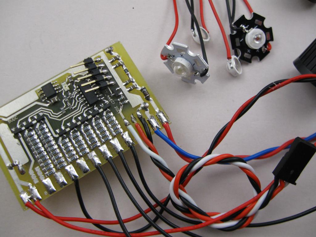
Power generally comes from a 3-cell Lipo battery, but it will operate up to 6-cells. This can be the main flight battery. The on-board regulator reduces this to a steady 9V to drive the LEDs. The servo lead connects to a spare channel on the RC receiver, allowing the LEDs to be turned off/on or mode changed in flight, ie. for landing lights. On-board are the resistors suiting 3 Watt LEDs. Each output can switch (sink) 1 Amp of current. Wiring is attached to the solder pads on the board edge. The Red-Blue in this picture is the main supply. The red wires at the other end are the LED +ve, the black wires the LED -ve. The board is configured with on-board resistors for 3W LEDs, so no additional resistors are required. We can supply the controller, 3W LEDs (in Green, Red, Blue and White), heatsink plates and 15-deg lenses. Because installation is very specific to each model, you can supply your own wiring. Although we do have quite a bit of the Red-Blue 0.5mm wiring available. |
Technical Stuff
The 9V LED supply allows two 3W LEDs to be run in series, which is more efficient. This allows red and green strobes to be wired and connected to one output (using matched LEDs). The red, green and white LEDs tested here all operate at a nominal 3.4V. A micro-controller manages the LEDs and monitors the PPM signal from the RC. If not using the PPM signal, it defaults to a standard flash pattern that suits most RC models. Using a servo tester or the RC, the default flash pattern can be selected from several pre-configured. The choice is saved and loaded at switch-on. On-Board LED ResistorsThe on-board LED resistors consist of arrays of surface mount resistors to help reduce heating. Most RC LEDs are flashing or strobes, so heating is usually minimal. See below for RC installation notes. The on-board resistors are sized to suit these 3W LEDs. 1W and smaller LEDs can be connected in combination or by adding external series resistors. For special application we can assemble these boards with other resistor values. |
LEDs and Wiring
LED voltage and currentLEDs operate on current, not voltage. You apply a voltage, if it is high enough current will flow, making the LED light, and heat up. The series connected resistor limits the current to a level that the LED can withstand. The voltage measured across the LED doesn’t matter except for power calculations. V x A = Watts. Using a fixed resistor value and a voltage supply works best if the supply voltage is steady. Not always the case with battery power. Constant-Current drivers are best, but more complex and more complex to configure when using assorted LEDs. Wire sizes depend on more on length as currents are not too high. Typical servo wire is usually OK. For large models where the LEDs may be spread out, you should increase the wire size slightly for the larger LEDs. 0.5mm flexible cable is good. The twisted Red-Blue wiring above is 0.5mm. Typical RC 3W White LEDI tested a Hobbyking 3W white LED (28504). These have a small metal heatsink disk and a short lead with servo connector attached. It only just starts to glow at 2.4V and gets brighter quickly as the voltage goes up. At the top end the current increases quickly and it gets very hot, even with the small metal heatsink. These tests done with a current limited power supply and temperature read with a IR thermometer (ambient was 24-degC):
This shows that beyond 1-1.5 Watts, additional heatsinking is a good idea if you don’t want to melt something or start a fire. At the top end, if you do want to run these at 3 watts, using a current limited supply is probably essential to making it reliable.. |
Our Other LEDs
If used as strobes they can be connected directly to the wiring and no heatsink is needed as the average power dissipation is minimal. When run for more than a few seconds at a time, the heatsink plates are needed. A small dot of thermal paste under the LED helps thermal conduction to the plate. For high power continuous use, an additional heatsink is required on the back of the plate. LED and Resistor Notes:
LEDs and the Controller Installed in RC modelsYou need to consider the heat generated by the LEDs and where it’s going to get out. Burying a high power LED in a foam wing will probably overheat the LED and melt the foam. You must also consider the time the model spends stationary on the ground in the sun, or on display with LEDs on. Heat will quickly build up and can melt glue and foam and will reduce the life of the LED. Multirotor installation is generally more open, with good air-flow during flight but you still need to make sure they don’t overheat when parked. Depending on the arrangement and number of LEDs, the controller may run warm. Most LEDs are strobed or flashed but landing lights may be on for longer periods and will cause the resistors to heat up. The controller may need a bit of air-flow; think of it like ESC or large BEC. Note: at a distance all LED colours tend to look the same but intensity varies compared with viewing close up. Just something to consider for FPV models. |
LED Accessories
|
| text |
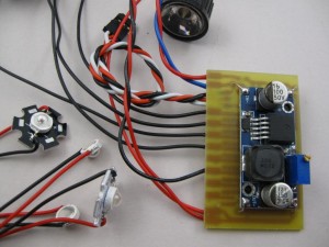 The main 9 volt regulator is on the back of the board. It is a standard switch-mode regulator that can supply up to 2 Amps or so. Peak current available for strobes is a bit higher.
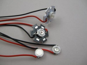 These are 3 Watt LEDs; although we do not run them at their full 3W rating. Heat is related to average power, not peak power.
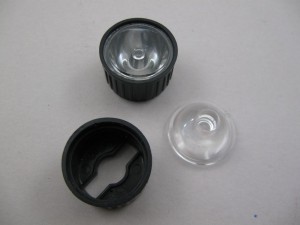 The lenses are available in various angles. As these are intended for beacons and landing lights we only have the 15-degree beam angle.