How it Works
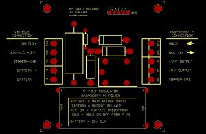
 In a vehicle application, it draws power from the AUX circuit which is live when the ignition is in the AUX and IGN positions. Turning on the IGN circuit activates the 5V and 12V outputs, turning on the R-Pi. In a vehicle application, it draws power from the AUX circuit which is live when the ignition is in the AUX and IGN positions. Turning on the IGN circuit activates the 5V and 12V outputs, turning on the R-Pi.
When IGN is turned off the 5V and 12V outputs remains powered for 2 minutes from the AUX circuit if still live, or the battery. The outputs remain on as long as the IGN is on.
The R-Pi can hold power ON by keeping the HOLD input high (3.3V). When the HOLD input goes low, the power goes off after after 3 seconds.
The ACC output on the R-Pi side is an indication that can be monitored by the R-Pi. It can be directly connected to the expansion I/O. A High (1) indicates that the ACC vehicle supply is ON.
Battery
For backup or limited operation beyond the IGN/AUX circuits going off, a smaller 1.3Ah SLA battery can be connected. A 3-Amp fuse should be installed in the battery +ve line. The board supplies limited battery charge current from the AUX supply. The battery voltage will float up to about 0.6V below the AUX voltage.
The AUX supply voltage should be generally only 0.5V higher than can be applied to the battery long term. This means about 14.3V if using a SLA battery – suitable for in vehicle use.
A battery such as a 8-cell NiMh can be used if the AUX supply voltage is reduced accordingly; approx. 10.5V, therefore not recommended for 12V vehicle use, but may be used in other areas.
Raspberry Pi Control
There are likely many ways this can be used. This is just one example:
The Hold input and ACC output are connected to R-Pi expansion I/O pins. When powered up, the R-Pi outputs high (1) to HOLD. The R-Pi now has control over the power supply. Monitoring the ACC input will tel the R-Pi when the ACC goes OFF. The R-Pi can complete and tasks remaining and shut-down, which releases HOLD. 3-seconds later power is turned off.
Auto-Start
Although not included in this design, a separate Real-Time-Clock (RTC) module could be arranged to trigger power-up. Just a thought.
|