 This unit was designed to connect up to 4 signs to one light sensor while isolating the signs from each other. Using one light sensor makes it easier to syncronize dimming of all signs as light levels change.
Electrical isolation between the signs prevents any problems with power supplies and earthing, and keeps the sign controllers isolated from each other.
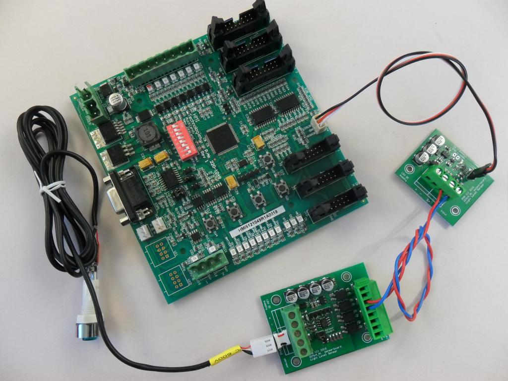
This image shows a sign controller board,light sensor, sender board connected via the #3 output to a receiver board. Three other receiver boards can be connected to the other outputs on the sender board and located in other signs, typically on a gantry.
How it works
One resistive light sensor (cds cell) is connect to a sender unit which a produces a digital signal that is optically isolated to 4 channels. Wiring to each sign connects to a smaller module which converts the digital signal to a light level and connects to the light sensor input.
Note: the sign with the sender board also needs a receiver board. This is to keep them all matched.
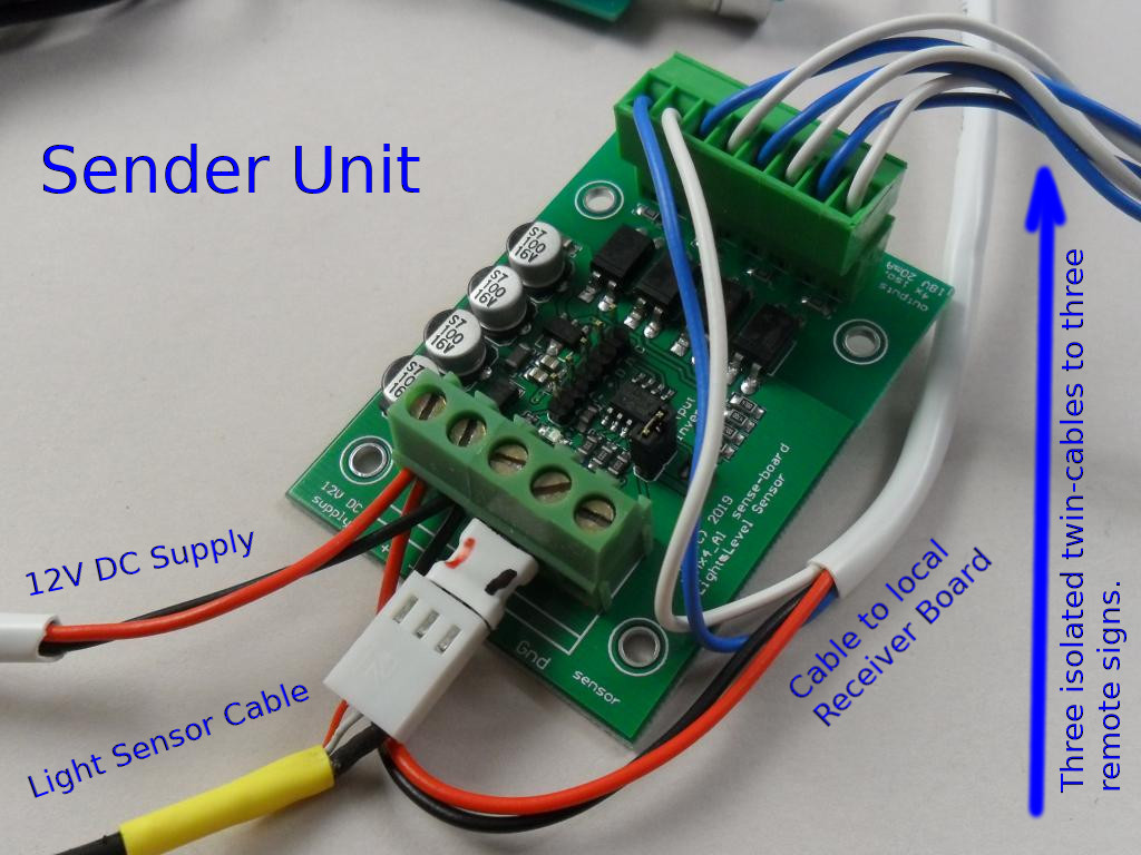
Sender unit
 This would normally be mounted in one of the signs – probably the one located in the best spot for the light sensor considering sunlight and shade from buildings, hills, trees etc.
This needs 12V DC power from a nearby supply, probably the sign controller. Connect the light sensor to the sender unit. Polarity may matter if the sensor contains a capacitor (red wire +ve) but will not matter for a simple cds cell sensor.
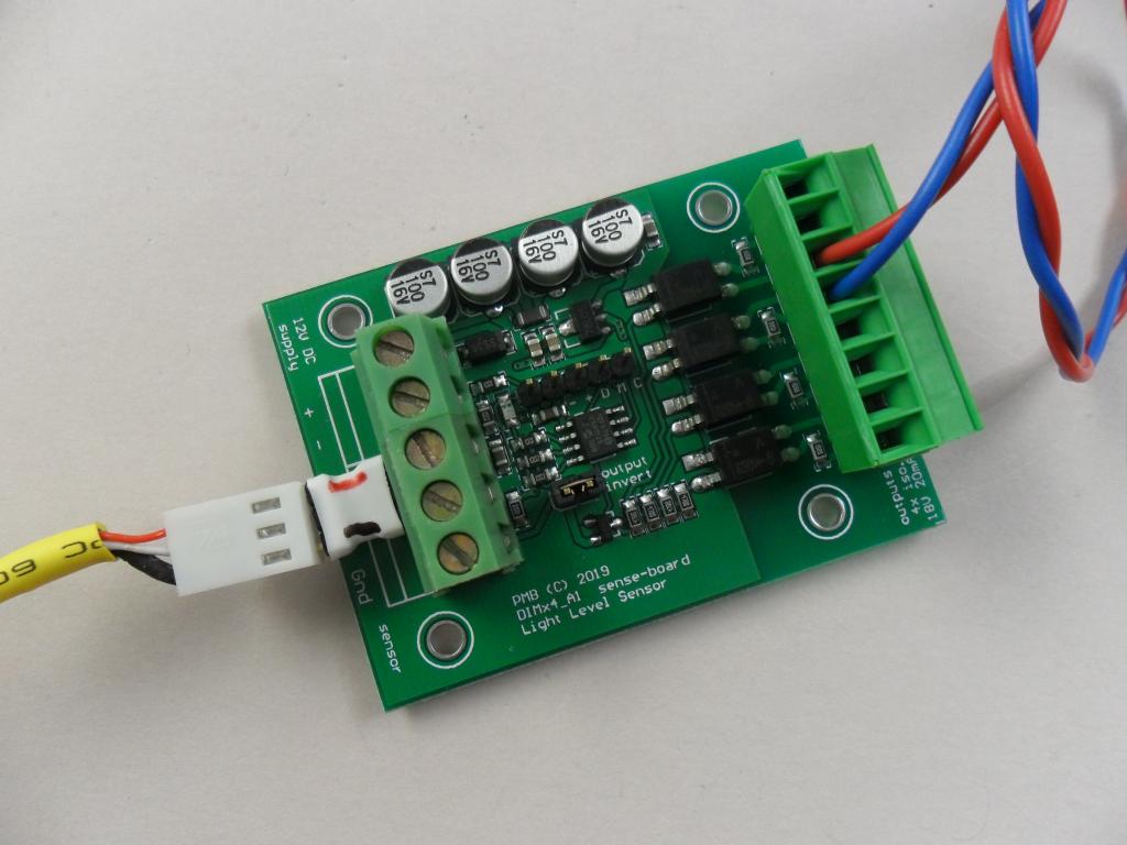
There are 4 outputs, each a opto-couple transistor which is polarity sensitive and run one output to each sign to a receiver board.
The INVERT jumper inverts the data to the receiver board effectively inverting the the light level seen by all 4 sign controllers. Typically this will remain ON (jumper in place).
 Specification:
- Power, 12VDC – 9-15V DC at 50mA max
- Power input reverse-polarity protected
- Light sensor 10K CDS – resistive sensor
- Outputs: 4x opto-coupler open-collector
- Outputs: current limit 100 ohm resistor
- Invert jumper: remove to invert output
- .
Receiver board
 This needs 12V DC power from the sign controller. It takes the digital signal which is polarity sensitive and feeds a DC light level voltage to the sign controller – where the light sensor used to connect.
Specifications:
- Power, 12VDC – 9-15V DC at 25mA max
- Power input reverse-polarity protected
.
Board mounting
There are mounting holes for 3mm screws. The boards can also be mounted using double sided stick foam. The foam must be thick enough – two layers of 2mm recommended. However, no foam is permanent and we recommend a small bead of neutral-cure silicon along 2 sides to ensure long term mounting security. “Roof and Gutter” sealant is neutral cure.
Electrical tape is a definite NO as it quickly goes gooey and comes off. Cable ties are not recommended unless it can be assured that the board will never contact any metal or other wiring.