Wire heating power supply – 25+Amps


stainless wire heating

1.5mm stainless wire – Testing

This was a small one-off project due to the need to heat 120mm long pieces of 1.5mm stainless steel wire as part of an industrial process.

It had to be quick, simple and safe.

In total, about 7 hours work from initial evaluation to boxed and ready to connect to the jig. About NZ$150 in parts; some from Jaycar, some from the junk box.

stainless wire heatingHow to do it

The heating current could be AC, so a transformer with a primary side control seemed logical. Quick and simple required off the shelf parts and Jaycar Electronics had some toroidal transformers and a mains power dimmer-controller.

I guessed a 160VA transformer would be large enough and toroidal would make it easy to add a low-voltage, high-current additional winding. The original secondary windings are not used; just left unconnected. The dimmer-controller is rated at 600 watts continuous and 1200 watts short-duty. It is described on the box as a “motor and lamp controller (dimmer)” so it should survive driving the transformer.

Some testing showed the ss-wire to have a cold resistance of 0.054 ohms per 100mm length. 1.5V applied would draw about 28 Amps and dissipate 40 watts. A 6 turn secondary winding of ??-wire provided 1.5V under some load. So to allow for some connection losses, increased resistance when hot and a bit of control headroom I put 18 turns on the secondary. As it worked out the voltage across the ss-wire is about 3V at 20 Amps which makes a nice red glow. 25 Amps makes a bright red glow at about 3.8V across the wire.

  • The transformer is a MT2112 12V + 12V 160VA toroidal with a secondary of 18 turns of 154 automotive cable (looks to be about 2.5mm)
  • The controller is also from Jaycar, a Kemo M012.

stainless wire heatingConstruction

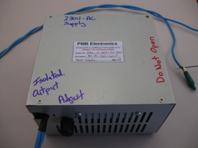
It had to be constructed into a box to be safe. The 500K potentiometer of the controller is live at mains potential on the terminals but has a plastic body and shaft, and plastic knob. The potentiometer is pretty crappy quality, but safe for the user. It also needed a fuse on the incoming mains just in case the controller failed or the output was directly shorted; although a short may not blow the mains fuse.

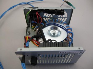
A failed PC power supply provided the enclosure. Metal, ventilated, earthed and pre-wired with IEC mains connector and power switch. A couple of holes drilled and some assembly required. A couple of hours and construction was complete.

Testing and Protection

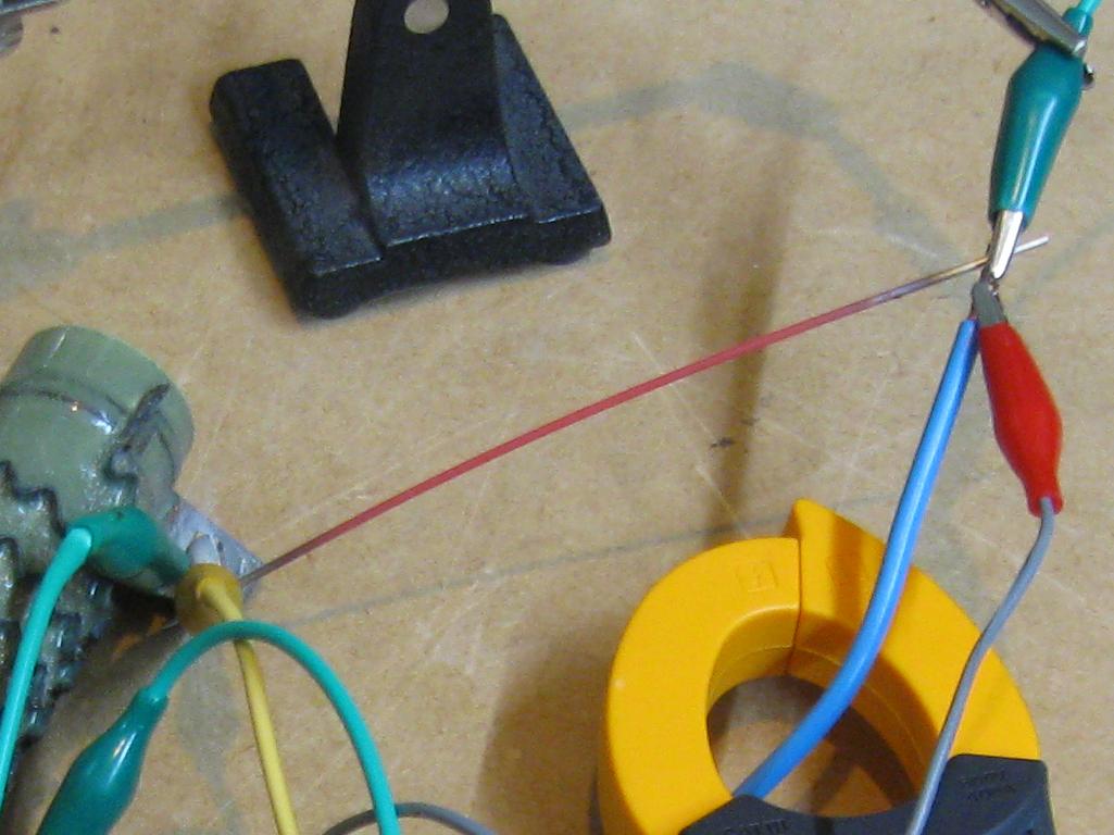
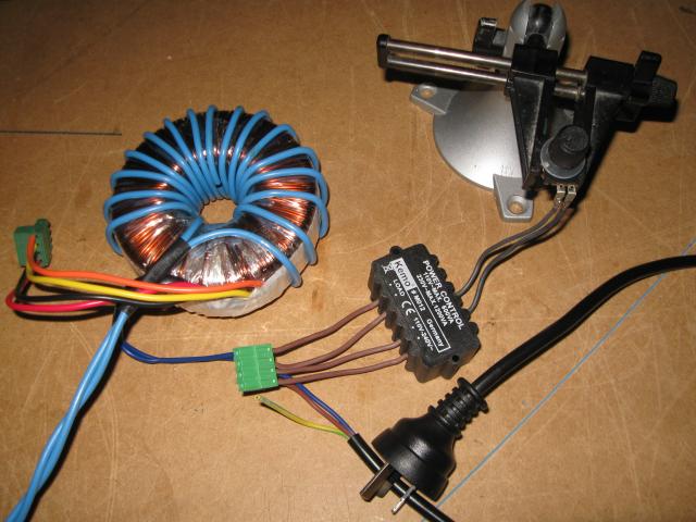
The main question is: will the controller survive? It’s a phase controller, probably leading edge as this is cheap and simple using a Triac. Just a standard light dimmer really, but we hope a bit more robust. The transformer is an inductive load and buzzes at low power settings as there are only short sharp energy pulse being applied. At higher power, more of the AC waveform is applied. This messes with the clip-on ammeter; sometimes it reads, sometimes it’s way off.

The power is adjusted using the knob. 3/4 travel is about 22 Amps with this wire.  Shorter wire lengths will draw more current up to a point. There is resistance in the transformer winding and output lead that will limit the maximum current at some point. A output fuse is a possibility but will add a volt-drop and will probably need screw terminals to be reliable.

The controller has survived testing with a standard ss-wire, being ramped up and power applied at a 3/4 setting onto a cold wire.

stainless wire heatingOperation

Power supply is 230-240V AC.

To begin with keep it simple. A jig holds the wire and connects the power supply output to the SS-wire.

Switch on and increase the current slowly. It takes a few seconds for the temperature to respond. Complete the operation and switch off.

If it is found that the current does not need constant adjustment, the setting can be left and the power supply just switched on when the ss-wire is ready.

Longer lengths or thinner ss-wire may not work the same due to the low output voltage limiting the current supplied.

DO NOT SHORT THE OUTPUT

There is a fuse inside the unit (3A, 3AG) If it stops working, check the fuse and replace with the same type. If the fuse blows again then the controller has possibly failed. Make sure it is disconnected from the mains power before replacing the fuse.

Safety

Under normal conditions the power supply output is not dangerous. It is supplying about 5V-AC (open circuit voltage) and is isolated from mains power.

Other than that common sense applies: Keep dry. Do not use if damaged. Do not take it apart.

Leave a comment