Testing and Repair
 Turning it on and all seemed OK. The small radio scanner showed that there was no signal transmitted; at least not in the 40MHz band. Turning it on and all seemed OK. The small radio scanner showed that there was no signal transmitted; at least not in the 40MHz band.
Maybe the crystal or part of the transmitter circuit had failed.
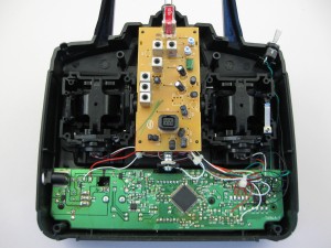
Next, open it up and run it from a bench power supply (10V). Current draw was about 30mA; not enough if the transmitter was running. Check the TX board for power (10V) and PPM signal. No PPM signal suggested maybe there was no output from the main board.
There was a PPM signal in there. But the open collector output had no pull-up so it must be on the TX board. Yes, and there is a 5V regulator for the first stages of the transmitter. There was 10V in, but no 5V out of the regulator.
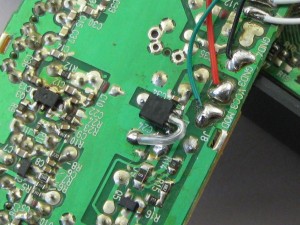
I replace it with a similar device (didn’t have the same package). Now we have 5V and PPM. Plugging in the crystal and the current draw rose to about 180mA; much better. The radio scanner now picks up the signal on the correct frequency.
 We run it for about 30 minutes to see that it keeps working and nothing gets hot; specifically, the new regulator. We run it for about 30 minutes to see that it keeps working and nothing gets hot; specifically, the new regulator.
This is a 78L05 in a TO-92 mounted to replace the original SMD regulator.
|