Thermal HuntingSubtle air temperature changes that indicate thermal activity are indicated on a meter or display to be interpreted by the pilot of a RC glider, or to suggest when to launch a free-flight model. OperationErect the pole and turn it on (or in the other order if it’s a tall pole). The unit will take a few minutes to stabilize and should sit on zero or mid scale with the gain control turned down. Increasing the gain setting will start the meter moving with smaller air temperature fluctuations. Remember to turn it off when finished. A 9V battery should last about 200 hours of operation, assuming a typical analog meter. |
Differential Temperature sensor
There are two temperature sensors connected in a bridge to an amplifier. One sensor is insulated from air movement and senses average ambient temperature. The other sensor is exposed in the air-flow (wind). As the air-flow temperature rises and falls relative to the average ambient temperature, the amplifier output voltage varies up and down around a centre null point. Analog Meter or DisplayThe best display is a good analog meter of the centre-zero type (1-0-1). Unfortunately, these are now rare and/or very expensive. A typical end-zero meter will always want to indicate negative and is not really suitable. You cannot adjust the zero point to preset a standard meter to the mid-point as it will drift and be affected by the gain setting. . |
Technical
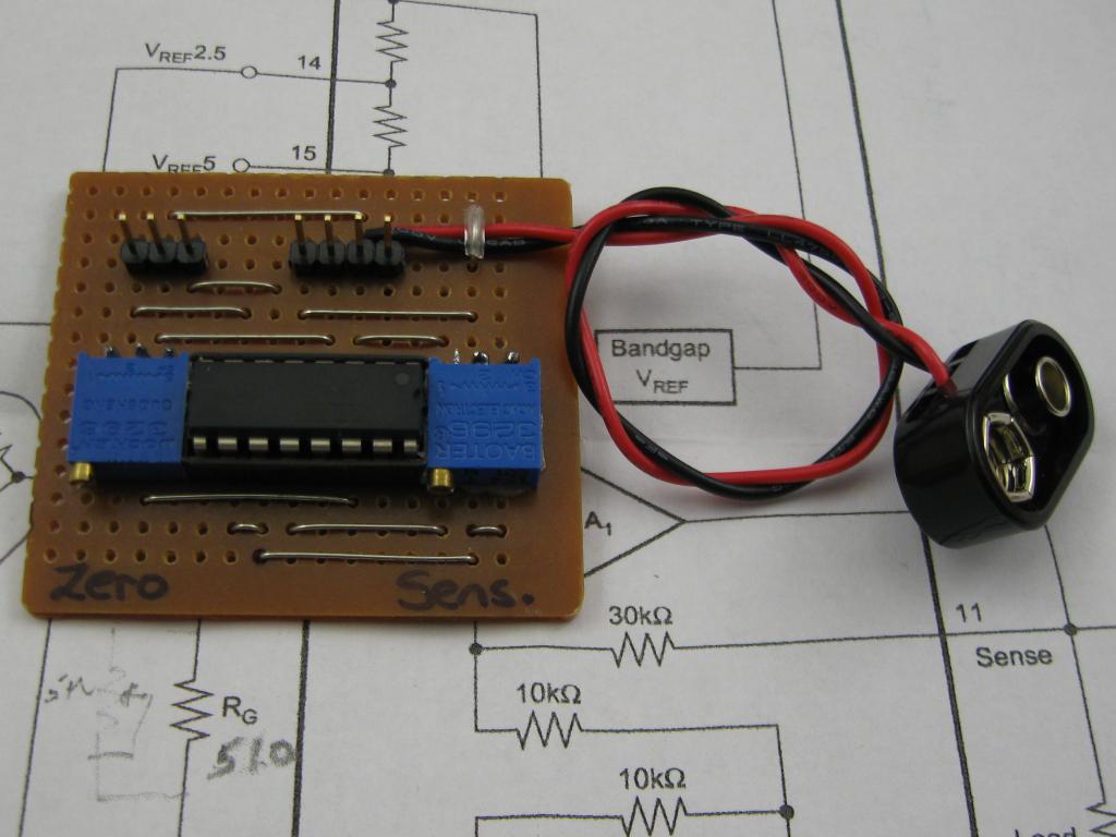
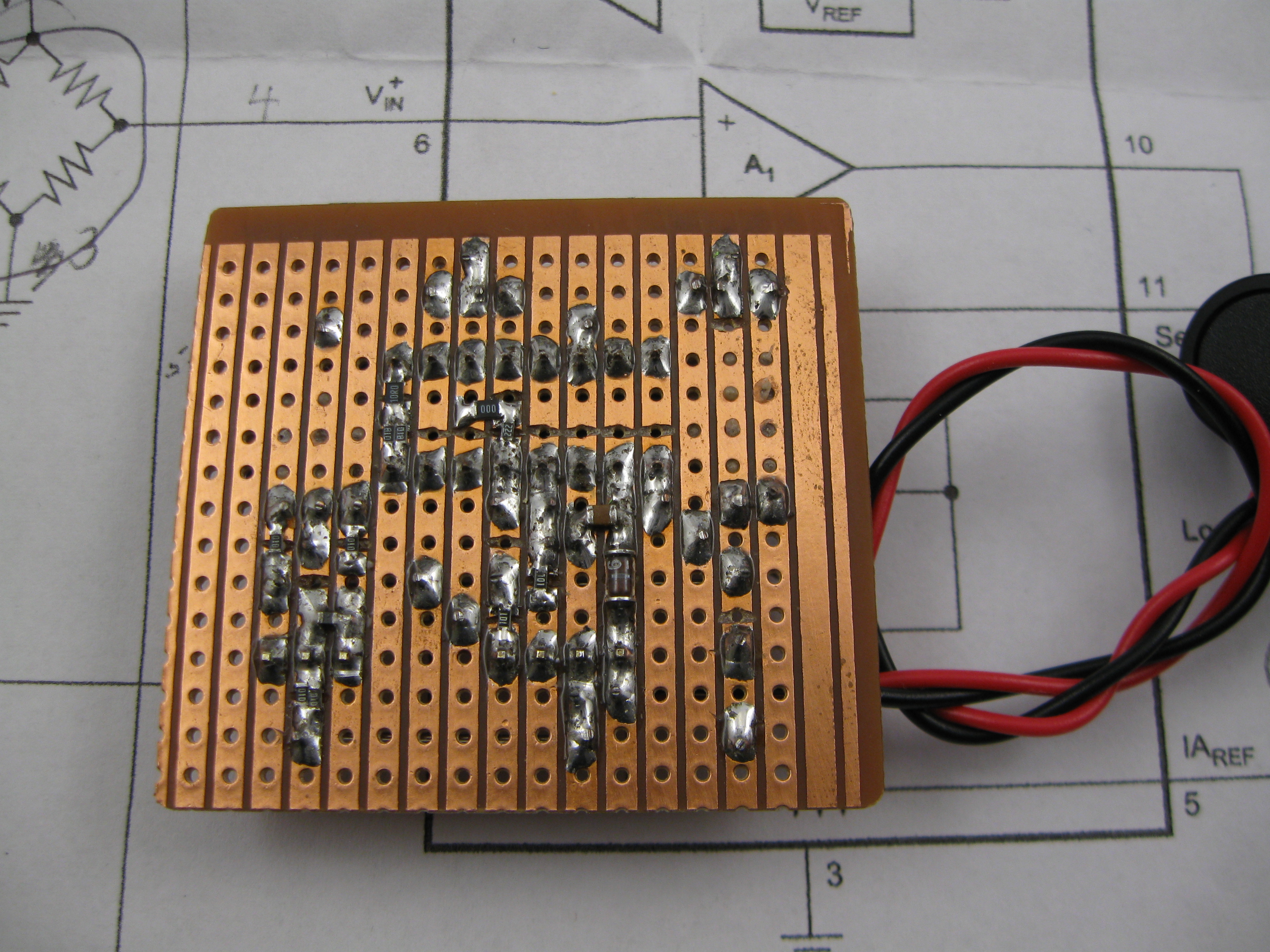
The sensors are small 10K 1% NTC thermistors. The amplifier is a INA125 instrumentation amplifier. The exposed sensor should have a very small thermal mass so that it responds to changes quickly. The ambient sensor is attached to the copper side of the circuit board. All of the small components are surface mount, smd types. The adjustment preset pots are to zero the bridge and adjust the meter sensitivity (in series with the output. An external potentiometer adjusts the gain of the amplifier. The power supply is a 9V alkaline battery. The current draw is 1 to 1.5 mA. [stextbox id=”info” caption=”Calibration and Adjustment” collapsed=”true”] Calibration and adjustmentWith the circuit powered for a while and stabilized, the external sensor needs to be at the same temperature as the ambient sensor and isolated from drafts. Adjust the ZERO preset to zero the output to the meter. The Sensitivity preset can be set to about half way (15-turns) for now and adjusted later if needed. It will depend on the meter used. [/stextbox] |