Why make a Light Switch
 I needed a Wifi connected light switch for the workshop, something a bit more robust than the usual indoor white plastic type. It had to run Tasmota – none of that Tuya stuff. So I built one based on some metal push buttons, supposedly waterproof, that I bought in from China.
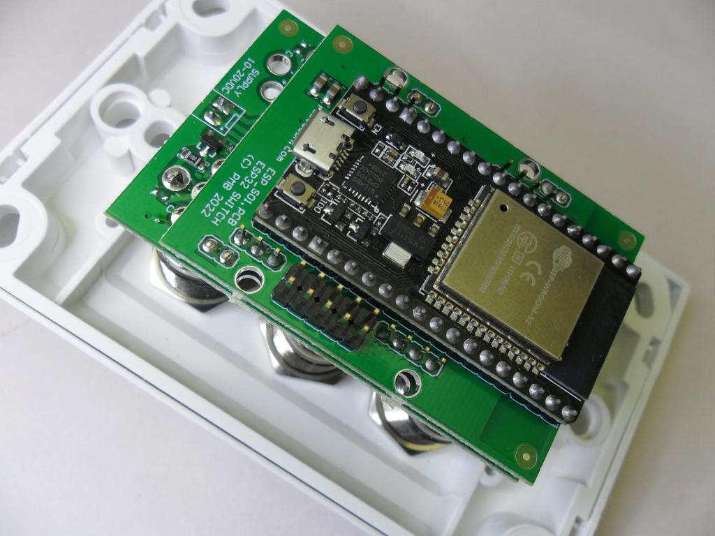
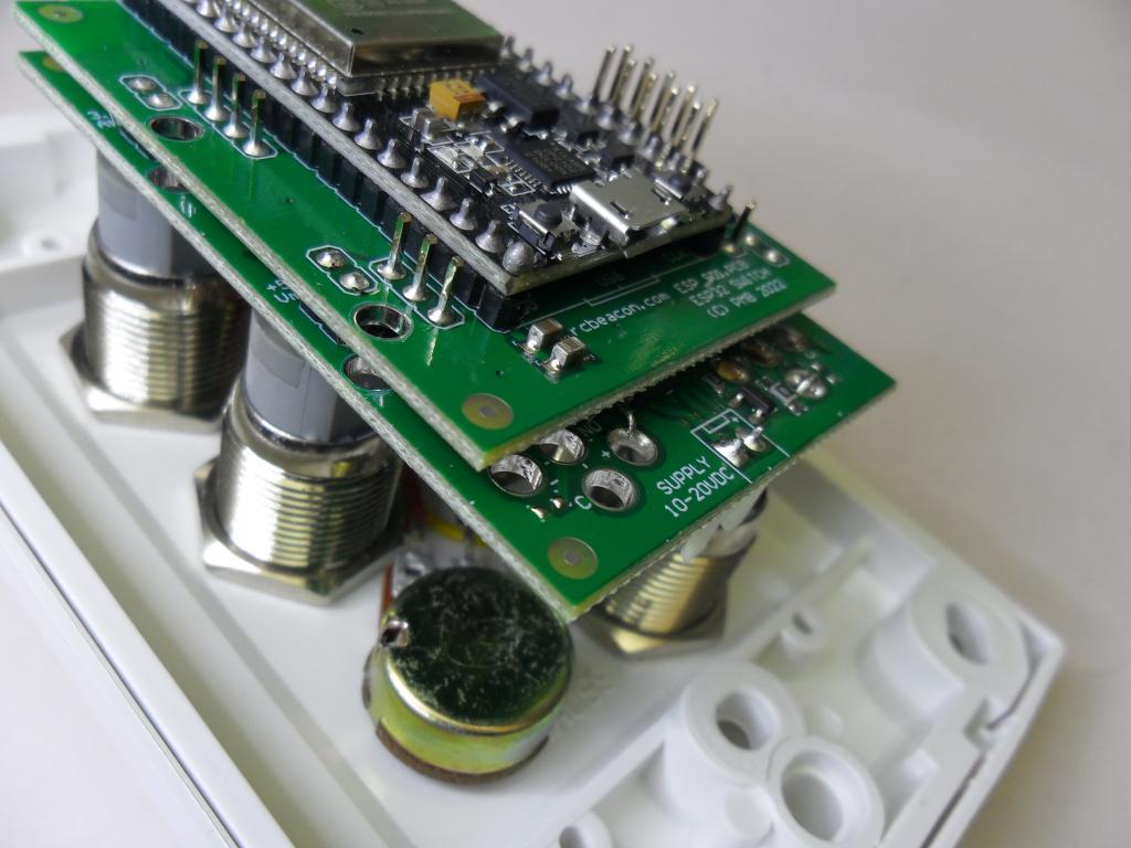
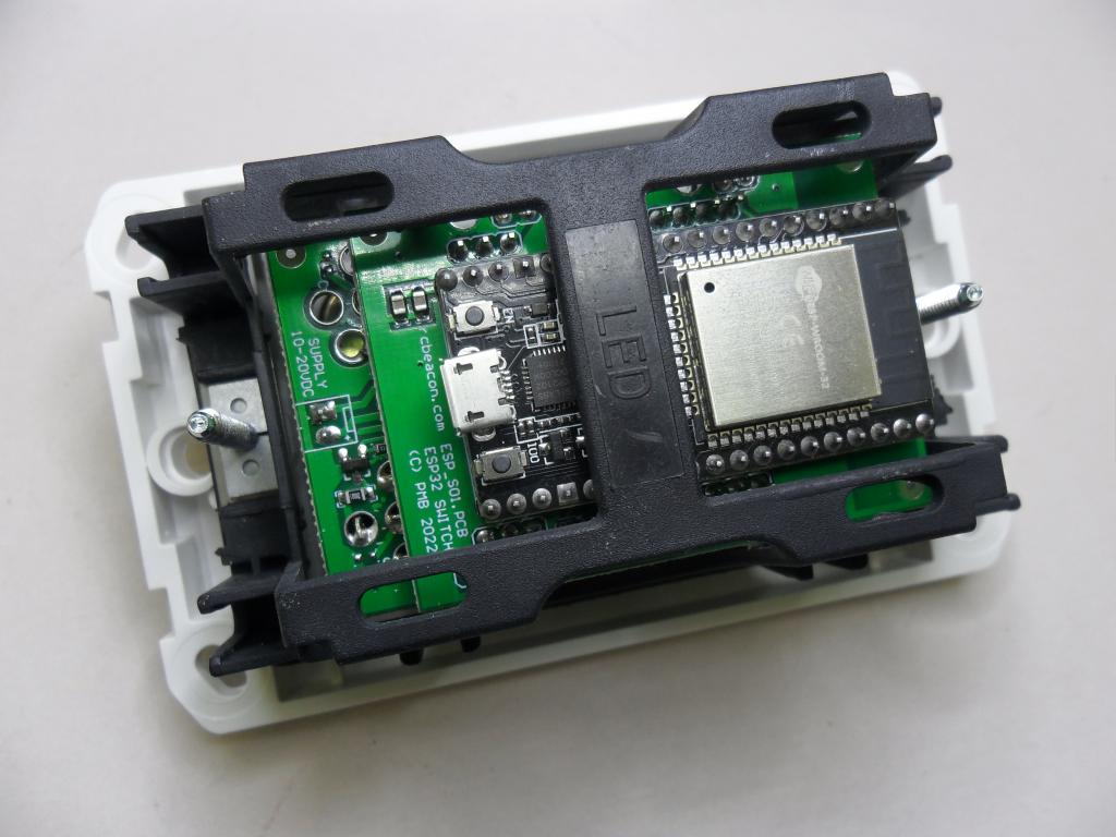
Thinking that I could use a few of these I didn’t want to manually wire each button and LED to a esp-32 module. A circuit board was designed. Due to the physical layout requirements of the buttons and the esp-32 module pin headers it became 2 circuit boards. This provided room for power supply regulator module and LED driver mosfets and a few header pins just in case we need a senor or two.
How Does it Work – a bit more technical
 It fits into a standard NZ electrical Flush-Box. All it requires is a 10-20V DC power supply. You need to know a bit about Tasmota and what you want to d with it to get it working. I have it connected to Home Assistant which is then controlling seven circuits of LED lighting, about 200 watts in total, via a couple of H801 wifi LED drivers.
The buttons have 12-24V LEDs fitted. The power supply fed the LEDs directly and is regulated down to 5V for the esp32 module. The power supplied could be 10-20V without exceeding any ratings.
The knob is connected to an analog input of the esp32. Can be used as a dimmer control or other variable input.
Header Pins
On the back are a few pins that could be used to connect sensors, maybe for temperature, humidity or light level. With a bit more programming the switch could operate stand-alone and a controller.
GPIO
| L-R, T-B | I/O | I/O – Relay | Tasmota32 | |
| Analog | GPIO36 – analog range | Potentiometer | AdcGpio36 0,4095,0,100 | |
| Analog | GPIO39 – analog voltage | Supply Voltage | AdcGpio39 0,4095,-40,43 | |
| Button 1 | GPIO19 – button | GPIO21 – relay | ||
| Button 2 | GPIO35 – button | GPIO25 – relay | ||
| Button 3 | GPIO5 – button | GPIO18 – relay | ||
| Button 4 | GPIO33 – button | GPIO26 – relay | ||
| Button 5 | GPIO16 – button | GPIO17 – relay | ||
| Button 6 | GPIO13 – button | GPIO12 – relay |
Tasmota
 A sort of control operating system running on the esp32 module. The buttons and LED indicators are connected as I/O. Tasmota has some scripting ability or connects to something else like Home Assistant via wifi – it’s up to you.
There are probably other firmware options, like ESP Home, but I have only used Tasmota so far.
There is a bit of a learning curve and setup required to make best use of the switch.
Tasmota32 Template String:
{“NAME”:”PMB-Switch”,”GPIO”:[1,1,1,1,1,34,1,1,229,37,1,1,36,228,226,32,0,224,1,1,0,225,227,1,0,0,0,0,1,35,1,33,4864,0,0,11264],”FLAG”:0,”BASE”:1}
Would You Like One ?
 Let us know. We have parts to build a few of these and will make them available. I haven’t worked out a price yet but will do as time permits or inquiries demand.
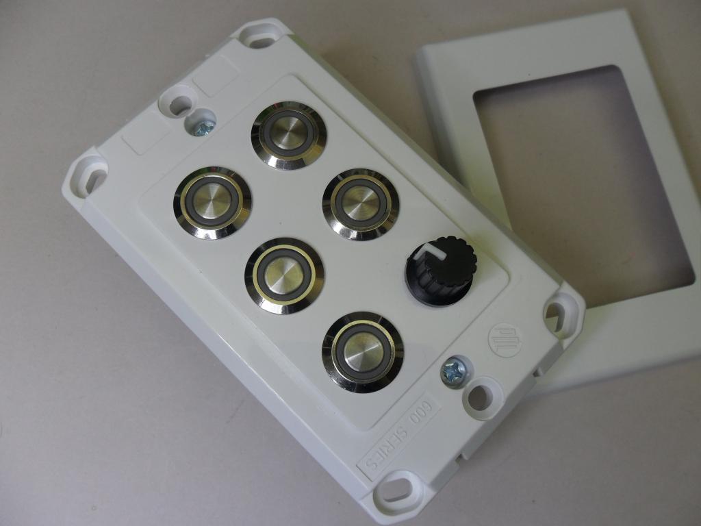
It can be assembled with up to 6 buttons or with one potentiomenter, knob. Probably 3 switches is a good minimum to securely support the circuit boards.