Hobbyking 5.8GHz 200mW FPV system
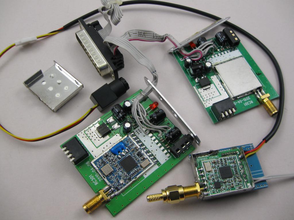
The 8 channel frequencies listed by Hobbyking are 5705 5865 5665 5645 5885 5905 5925 5945 MHZ. Note that the second one is a typo and should read 5685, which is not within the allowed 5725-5875 MHz band. The picture shows my transmitter with heatsink removed (just clips on) and connectors removed with camera and power wiring soldered. And 2 RC305 receivers out of their cases, one with the receiver module cover removed. The receivers have been wired to connect to the diversity controller. Ignore the wiring soldered to the boards, we’re only interested in the smaller RF modules. The antenna plug attached to the transmitter is a 50-ohm dummy load. Don’t run the transmitter without a load or antenna connected as you may damage it.
Note: You can run the receiver at more than 5V DC supply. It has an internal regulator and will cope with 12V or a 3-cell Lipo, but will get warm. |
Specifications from Hobbyking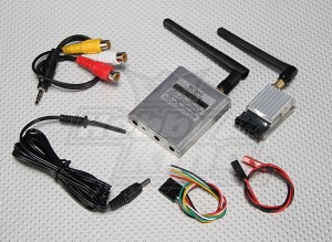 Image from Hobbyking Output impedance: 50 Ohm |
Modification for NZ 5.8GHz ISM bandThe ISM band here in New Zealand that allows up to 1 Watt eirp for this type of gear is within 5725-5875 MHz or 5.725 to 5.875 GHz. The chip-set used in this system has two control modes, 1. not-used here where a external micro-controller tells it what to do, 2. the mode used here where dip-switches select one of 8 preset channels. There are actually 24 channels in three banks of 8; A, B and E bands. The Hobbyking system is preset to E-band, but we want A-band. Two pins on the chip (TX and RX) select this and must be connected to 0V to select A-band. This is relatively easy as there are already small jumper locations on the board to do this. All we have to do is insert the jumpers; wire links or easier, zero-Ohm resistors. Note: there may be different versions of the units and the internal RF module that will affect these notes. A-Band frequencies are: 5865 5845 5825 5805 5785 5765 5745 5725. |
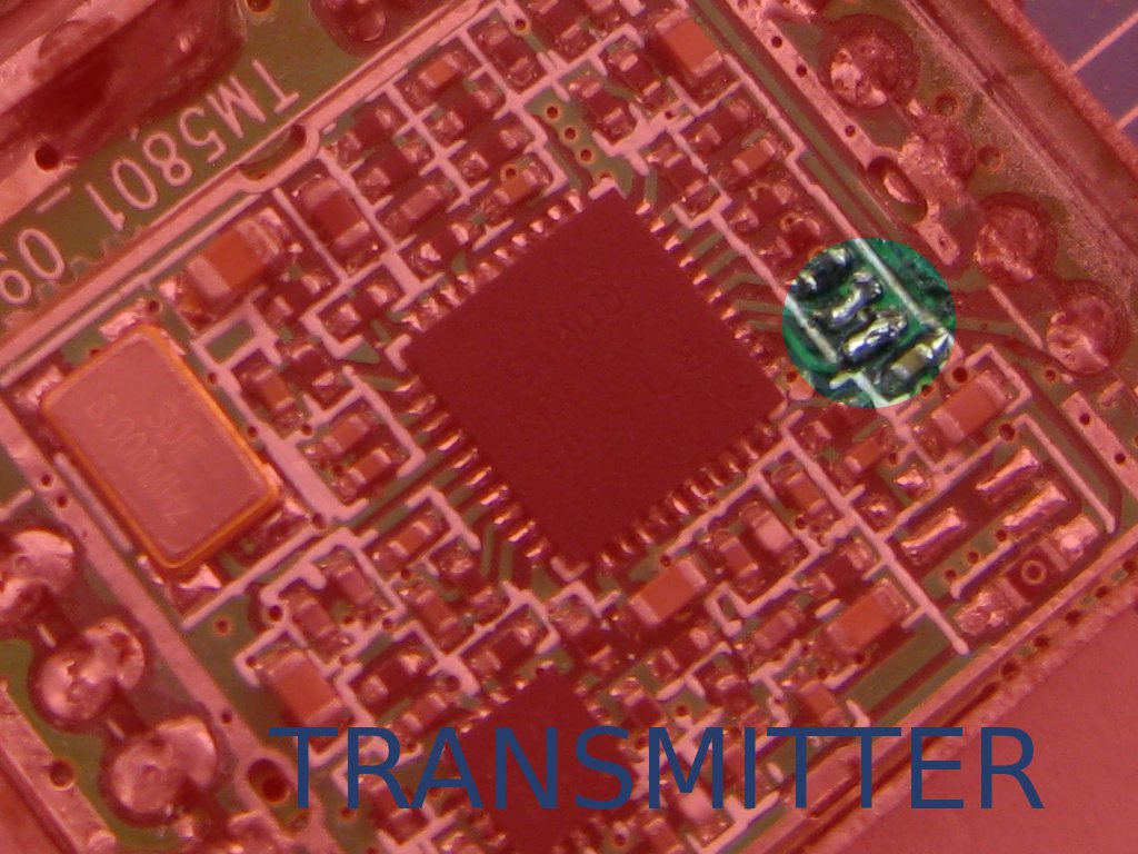
Transmitter Modification
A fine tip soldering iron and fine tweezers a required. Don’t touch anything else in there with the soldering iron. It’s very difficult (almost impossible) to reliably get a solder blob alone to bridge the gap being jumpered, but it will stick to everything else. When testing, power the transmitter and receiver from current limited power supplies. You must have a camera fitted to know if it’s working. Modify the transmitter before the receiver and check that the receiver no longer gets a signal; either you have changed bands or killed it 🙁 Modify the receiver and test again. it should be working again. |
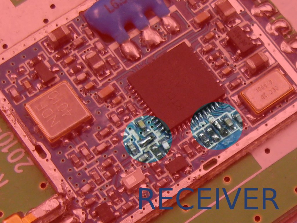
Receiver Modification
Add the two jumpers or links and test it before soldering the cover back on. A standard soldering iron is OK for replacing the metal cover. On the new frequencies you may see some interference if you have 5.8G wifi or cordless phones in the area. Current limited power supply trickUsing a battery for testing is a really bad idea. If anything goes wrong, there is nothing to limit the level of destruction you can achieve. For 5-15V testing you can connect a automotive incandescent lamp in series with the supply. If too much current flows the lamp till glow or light and limit the current through the fault. The lamp wattage is chose based on the expected current draw and is not too critical. 5W, 12W an 20W lamps (or close) will be handy. |
HobbyKing now have the Skyzone 5823 5.8 GHz 32 ch 200 mW vid Tx :
http://www.hobbyking.com/hobbyking/store/uh_viewitem.asp?idproduct=63114
and looking at the published specs I see that of these 32 ch available, 23 ch are within our legal ISM range. Plus in keeping with the name it’s smaller than the ‘regular’ TS 351 and weighs in at only 8g but still pumps out 200 mW
andy
Yes these are quite nice, and small.
Unfortunately, because they are capable of transmitting out of band on a few channels, they are technically not allowed.
I have one here but haven’t had a good play with it yet. From memory, one or two of the channel select dip switches swap banks/bands. If these could be permanently fixed to select 8 channels within our ISM band, you’d possibly be OK; who can say for sure when regulations are involved 🙂